
Homework Answers
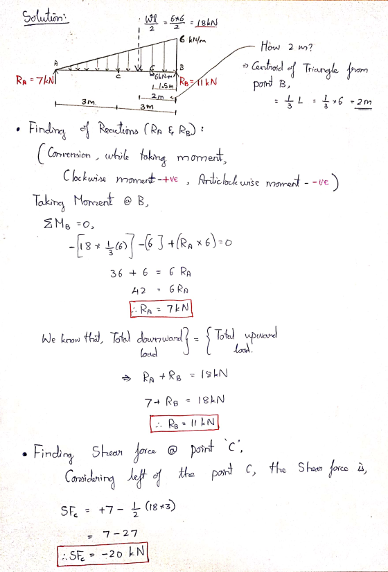

At point C,
Shear force= -20kN
Bending moment= -6kNm
While calculating shear force and bending moment, we can consider either left or right of the section .
Here, I have taken left side of point C, for easier calculations. If we consider right side , we will get the same answer.. but to avoid tedious calculations (bcz of trapezoidal shape) I considered left side of point C.
Add Answer to:
1- Determine the shear and moment at point C for the beam shown in the figure....
1- Determine the shear and moment at point C for the beam shown in the figure....
 1- Determine the shear and moment at point C for the beam shown in the figure. 6KN/ BKN.m from 1,5m Зm Зm
Question 2: A simply supported beam under loading as shown in Figure 1: 1. Draw the influence lines of the bending moment and shear force at point C (L/4) Using the influence lines to determine t...
 Question 2: A simply supported beam under loading as shown in Figure 1: 1. Draw the influence lines of the bending moment and shear force at point C (L/4) Using the influence lines to determine the bending moment and shear force at section C due to the loading as shown in the figure. 2. 3. There is a distributed live load (w#2.5kN/m) which can vary the location along the beam. Determine the location of the live loads which create the...
Problem-1: Calculate reactions, point of zero shear, maximum shear and moment, and point of contraflexure of...
 Problem-1: Calculate reactions, point of zero shear, maximum shear and moment, and point of contraflexure of the beam shown in Figure 1. Also, draw shear and moment diagrams for the beam. 9 kN/m 9 kN/m Figure-1 3 m 3 m
determine the normal force,shear force and bending moment at C of the beam in the figure...
 determine the normal force,shear force and bending moment at C
of the beam in the figure
Determine the normal force, shear force, and bending moment at C of the beam in the figure. 25 kips 10
determine the normal force,shear force and bending moment at C
of the beam in the figure
Determine the normal force, shear force, and bending moment at C of the beam in the figure. 25 kips 10
4. For the beam and loading shown, draw the shear force and bending moment diagrams and...
 4. For the beam and loading shown, draw the shear force and bending moment diagrams and determine the maximum bending and shear force and their locations. 20 KN 40 KN B D 250 mm |--2.5 m- 3m-4-2 m 80 mm 5. For the beam and loading shown, draw the shear force and bending moment diagrams and determine the maximum bending and shear force and their locations. 50 KN
Duration: 100 min Q1- Draw the shear and moment diagrams for the beam shown in figure...
 Duration: 100 min Q1- Draw the shear and moment diagrams for the beam shown in figure and calculate the maximum bending stress. (70%) 4KN 2KN V B cross-section 3m + 1m Im 3m
2. Determine all support reactions and draw shear and moment diagrams of the beam shown below...
 2. Determine all support reactions and draw shear and moment diagrams of the beam shown below by using the Moment Distribution method (10 points) 5 T/m 21 A DB 3m ΑΙΙ ΕΙ 10 T 2m 5m
For the beam shown in the figure below a. Draw the shear and moment diagrams for this beam
 For the beam shown in the figure below a. Draw the shear and moment diagrams for this beam b. Calculate the maximum bending stress, maximum axial stress, and maximum shear stress acting on the beam cross section c. Sketch the distributions of shear stresses and bending stresses acting on the beam cross section at the locations where these stresses are maximum.
Q 4. A beam is shown in the figure given below where A is hinged, and...
 Q 4. A beam is shown in the figure given below where A is hinged, and B and C are roller supports. Use Three-Moment-Theorem to determine the end moments and draw the BMD for the beam. w kN/m P2 kN P1 kN B A D 2EI 2EI EI L4 L3 L3 L2 L1. in Given values: L1=4m, L2=3m, L3=3m, L4=2m, P1=6KN, P2=8KN, W=8kn/m
Q5: Using force method, determine the reactions of the supports for the beam shown in Figure...
 Q5: Using force method, determine the reactions of the
supports for the beam shown in Figure (5). Then draw shear and
bending moment diagrams for the beam. EI is constant. Use conjugate
beam method to determine deflections.
I need it in 30min or 1 h
6 m 50 KN 200 kN.m 22 А В. С 9 m to 3m
Q5: Using force method, determine the reactions of the
supports for the beam shown in Figure (5). Then draw shear and
bending moment diagrams for the beam. EI is constant. Use conjugate
beam method to determine deflections.
I need it in 30min or 1 h
6 m 50 KN 200 kN.m 22 А В. С 9 m to 3m
 1- Determine the shear and moment at point C for the beam shown in the figure. 6KN/ BKN.m from 1,5m Зm Зm
 Question 2: A simply supported beam under loading as shown in Figure 1: 1. Draw the influence lines of the bending moment and shear force at point C (L/4) Using the influence lines to determine the bending moment and shear force at section C due to the loading as shown in the figure. 2. 3. There is a distributed live load (w#2.5kN/m) which can vary the location along the beam. Determine the location of the live loads which create the...
 Problem-1: Calculate reactions, point of zero shear, maximum shear and moment, and point of contraflexure of the beam shown in Figure 1. Also, draw shear and moment diagrams for the beam. 9 kN/m 9 kN/m Figure-1 3 m 3 m
 determine the normal force,shear force and bending moment at C
of the beam in the figure
Determine the normal force, shear force, and bending moment at C of the beam in the figure. 25 kips 10
determine the normal force,shear force and bending moment at C
of the beam in the figure
Determine the normal force, shear force, and bending moment at C of the beam in the figure. 25 kips 10
 4. For the beam and loading shown, draw the shear force and bending moment diagrams and determine the maximum bending and shear force and their locations. 20 KN 40 KN B D 250 mm |--2.5 m- 3m-4-2 m 80 mm 5. For the beam and loading shown, draw the shear force and bending moment diagrams and determine the maximum bending and shear force and their locations. 50 KN
 Duration: 100 min Q1- Draw the shear and moment diagrams for the beam shown in figure and calculate the maximum bending stress. (70%) 4KN 2KN V B cross-section 3m + 1m Im 3m
 2. Determine all support reactions and draw shear and moment diagrams of the beam shown below by using the Moment Distribution method (10 points) 5 T/m 21 A DB 3m ΑΙΙ ΕΙ 10 T 2m 5m
 Q 4. A beam is shown in the figure given below where A is hinged, and B and C are roller supports. Use Three-Moment-Theorem to determine the end moments and draw the BMD for the beam. w kN/m P2 kN P1 kN B A D 2EI 2EI EI L4 L3 L3 L2 L1. in Given values: L1=4m, L2=3m, L3=3m, L4=2m, P1=6KN, P2=8KN, W=8kn/m
 Q5: Using force method, determine the reactions of the
supports for the beam shown in Figure (5). Then draw shear and
bending moment diagrams for the beam. EI is constant. Use conjugate
beam method to determine deflections.
I need it in 30min or 1 h
6 m 50 KN 200 kN.m 22 А В. С 9 m to 3m
Q5: Using force method, determine the reactions of the
supports for the beam shown in Figure (5). Then draw shear and
bending moment diagrams for the beam. EI is constant. Use conjugate
beam method to determine deflections.
I need it in 30min or 1 h
6 m 50 KN 200 kN.m 22 А В. С 9 m to 3m
Most questions answered within 3 hours.
-
Sparky, Co. purchased land as a factory site for $600,000.
Sparky paid $42,000 to tear down...
asked 6 minutes ago -
A Chi-square distribution with 14 degrees of freedom is a
correct model for
Question 8 options:...
asked 35 minutes ago -
In a group of 45 mice, there are 10 that have a certain genetic
character. suppose...
asked 17 minutes ago -
Topic: Hydrogenic Atoms
The wavefunction of one of the d orbitals is proportional to sin
θ...
asked 17 minutes ago -
6. Suppose that the Bank of Canada conducts an open market
purchase of $2000 from a...
asked 32 minutes ago -
A) Suppose U=X∙Y3. Find X* and Y*.
B) Suppose U=X3∙Y. Find X* and Y*.
C) Suppose...
asked 40 minutes ago -
The only quantities of good 1 that Barbara can buy are 1 unit or
zero units....
asked 30 minutes ago -
c. Node Admittance matrix and its use in different calculations
of power transmission system. Display the...
asked 38 minutes ago -
Try to get the code down to less than 40 lines. (PYTHON)
import random
fave_number =...
asked 38 minutes ago -
2.
Regression analysis was applied between sales (in $1,000) and
advertising (in $100), and the following...
asked 46 minutes ago -
I just took a final for chemistry 2. There were alot of
questions on cell potential....
asked 1 hour ago -
A spherical weather balloon is filled with hydrogen until its
radius is 2.30 m. Its total...
asked 43 minutes ago