
Homework Answers


Add Answer to:
a) Consider the control system in Figure 2(a). Determine the transient response characteristics (rise time, peak...
a) Consider the control system in Figure 2(a). Determine the transient response characteristics (rise time, peak...
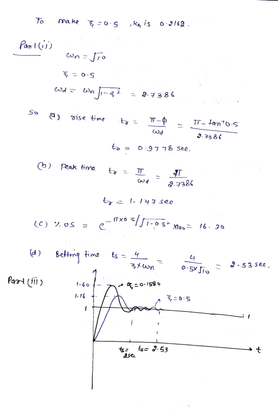
 a) Consider the control system in Figure 2(a). Determine the transient response characteristics (rise time, peak time, maximum overshoot and settling time) and the steady state error for the system. (2 marks) b) To improve the relative stability, the tachometer feedback are employed as shown in Figure 2(b). i Determine the value K, so that the damping ratio of the system is 0.5. (1 % marks) ii. From the result obtained in (), evaluate the transient response characteristics (rise time,...
. a) Consider the control system in Figure 2(a). Determine the transient response characteristics (rise time,...
 .
a) Consider the control system in Figure 2(a). Determine the transient response characteristics (rise time, peak time, maximum overshoot and settling time) and the steady state error for the system. (2 marks) b) To improve the relative stability, the tachometer feedback are employed as shown in Figure 2(b). i. Determine the value Kn so that the damping ratio of the system is 0.5. (1 % marks) ii. From the result obtained in (), evaluate the transient response characteristics (rise...
.
a) Consider the control system in Figure 2(a). Determine the transient response characteristics (rise time, peak time, maximum overshoot and settling time) and the steady state error for the system. (2 marks) b) To improve the relative stability, the tachometer feedback are employed as shown in Figure 2(b). i. Determine the value Kn so that the damping ratio of the system is 0.5. (1 % marks) ii. From the result obtained in (), evaluate the transient response characteristics (rise...
Question 2 a) Consider the control system in Figure 2(a). Determine the transient response characteristics (rise...
 Question 2 a) Consider the control system in Figure 2(a). Determine the transient response characteristics (rise time, peak time, maximum overshoot and settling time) and the steady state error for the system. (2 marks) b) To improve the relative stability, the tachometer feedback are employed as shown in Figure 2b). i Determine the value in so that the damping ratio of the system is 0.5. (1 % marks) From the result obtained in , evaluate the transient response characteristics (rise...
Question 2 a) Consider the control system in Figure 2(a). Determine the transient response characteristics (rise...
 Question 2 a) Consider the control system in Figure 2(a). Determine the transient response characteristics (rise time, peak time, maximum overshoot and settling time) and the steady state error for the system. (2 marks) b) To improve the relative stability, the tachometer feedback are employed as shown in Figure 2(b). i Determine the value Kso that the damping ratio of the system is 0.5. (1 % marks) i. From the result obtained in (), evaluate the transient response characteristics (rise...
Question 2 a) Consider the control system in Figure 2(a). Determine the transient response characteristics (rise...
 Question 2 a) Consider the control system in Figure 2(a). Determine the transient response characteristics (rise time, peak time, maximum overshoot and settling time) and the steady state error for the system. (2 marks) b) To improve the relative stability, the tachometer feedback are employed as shown in Figure 2(b). Determine the value K, so that the damping ratio of the system is 0.5. (1 % marks) i. From the result obtained in (), evaluate the transient response characteristics (rise...
question 2 Question 2 a) Consider the control system in Figure 2(a). Determine the transient response...
 question 2
Question 2 a) Consider the control system in Figure 2(a). Determine the transient response characteristics (rise time, peak time, maximum overshoot and settling time) and the steady state error for the system (2 marks) b) To improve the relative stability, the tachometer feedback are employed as shown in Figure 2(b). Determine the value Kin so that the damping ratio of the system is 0.5. (1 % marks) it. From the result obtained in 0. evaluate the transient response...
question 2
Question 2 a) Consider the control system in Figure 2(a). Determine the transient response characteristics (rise time, peak time, maximum overshoot and settling time) and the steady state error for the system (2 marks) b) To improve the relative stability, the tachometer feedback are employed as shown in Figure 2(b). Determine the value Kin so that the damping ratio of the system is 0.5. (1 % marks) it. From the result obtained in 0. evaluate the transient response...
1. Consider the unity feedback system shown in figure 1 with G(S) -2sti a) Determine the...
 1. Consider the unity feedback system shown in figure 1 with G(S) -2sti a) Determine the closed loop transfer function TF(s) γ(s) R(s) What are the poles and zeros of TF1(s)? [2 marks] b) For TF(s), calculate the DC gain, natural frequency and damping ratio. Classify TF1(s) as underdamped overdamped, critically damped or undamped [3 marks] c) Use the initial value theorem and final value theorem to determine the initial value (Mo) and final value (M) of the [2 marks]...
2. You are given the motor whose transfer function is shown in Figure 2(a). s) e(s) Amplifier Mot...
 Control system
2. You are given the motor whose transfer function is shown in Figure 2(a). s) e(s) Amplifier Motor C(s) 15 Tachometer Кр Figure 2 a) If this motor were the forward transfer function of a unity feedback system, calculate the percent overshoot and settling time that could be expected. b) You want to improve the closed-loop response. Since the motor constants cannot be changed and you cannot use a different motor, an amplifier and tachometer are inserted into...
Control system
2. You are given the motor whose transfer function is shown in Figure 2(a). s) e(s) Amplifier Motor C(s) 15 Tachometer Кр Figure 2 a) If this motor were the forward transfer function of a unity feedback system, calculate the percent overshoot and settling time that could be expected. b) You want to improve the closed-loop response. Since the motor constants cannot be changed and you cannot use a different motor, an amplifier and tachometer are inserted into...
QUICK UPVOTE: As a control system engineer you have been asked to design a controller that...
 QUICK UPVOTE:
As a control system engineer you have been asked to design a controller that would improve the error and the transient response for the unity feedback system below. The proposed solution must be cost-effective, so consider a passive network-based compensator. The transient response of the closed-loop transfer function to a ramp input has a 30% overshoot (%OS = 30) and a settling time Ts= 2.73 seconds. You need to decrease the peak time by a factor of 2,...
QUICK UPVOTE:
As a control system engineer you have been asked to design a controller that would improve the error and the transient response for the unity feedback system below. The proposed solution must be cost-effective, so consider a passive network-based compensator. The transient response of the closed-loop transfer function to a ramp input has a 30% overshoot (%OS = 30) and a settling time Ts= 2.73 seconds. You need to decrease the peak time by a factor of 2,...
1. Consider a unity feedback control system with the transfer function G(s) = 1/[s(s+ 2)] in...
1. Consider a unity feedback control system with the transfer function G(s) = 1/[s(s+ 2)] in the forward path. (a) Design a proportional controller that yields a stable system with percent overshoot less that 5% for the step input (b) Find settling time and peak time of the closed-loop system designed in part (a); (c) Design a PD compensator that reduces the settling time computed in (b) by a factor of 4 while keeping the percent overshoot less that 5%...
 a) Consider the control system in Figure 2(a). Determine the transient response characteristics (rise time, peak time, maximum overshoot and settling time) and the steady state error for the system. (2 marks) b) To improve the relative stability, the tachometer feedback are employed as shown in Figure 2(b). i Determine the value K, so that the damping ratio of the system is 0.5. (1 % marks) ii. From the result obtained in (), evaluate the transient response characteristics (rise time,...
 .
a) Consider the control system in Figure 2(a). Determine the transient response characteristics (rise time, peak time, maximum overshoot and settling time) and the steady state error for the system. (2 marks) b) To improve the relative stability, the tachometer feedback are employed as shown in Figure 2(b). i. Determine the value Kn so that the damping ratio of the system is 0.5. (1 % marks) ii. From the result obtained in (), evaluate the transient response characteristics (rise...
.
a) Consider the control system in Figure 2(a). Determine the transient response characteristics (rise time, peak time, maximum overshoot and settling time) and the steady state error for the system. (2 marks) b) To improve the relative stability, the tachometer feedback are employed as shown in Figure 2(b). i. Determine the value Kn so that the damping ratio of the system is 0.5. (1 % marks) ii. From the result obtained in (), evaluate the transient response characteristics (rise...
 Question 2 a) Consider the control system in Figure 2(a). Determine the transient response characteristics (rise time, peak time, maximum overshoot and settling time) and the steady state error for the system. (2 marks) b) To improve the relative stability, the tachometer feedback are employed as shown in Figure 2b). i Determine the value in so that the damping ratio of the system is 0.5. (1 % marks) From the result obtained in , evaluate the transient response characteristics (rise...
 Question 2 a) Consider the control system in Figure 2(a). Determine the transient response characteristics (rise time, peak time, maximum overshoot and settling time) and the steady state error for the system. (2 marks) b) To improve the relative stability, the tachometer feedback are employed as shown in Figure 2(b). i Determine the value Kso that the damping ratio of the system is 0.5. (1 % marks) i. From the result obtained in (), evaluate the transient response characteristics (rise...
 Question 2 a) Consider the control system in Figure 2(a). Determine the transient response characteristics (rise time, peak time, maximum overshoot and settling time) and the steady state error for the system. (2 marks) b) To improve the relative stability, the tachometer feedback are employed as shown in Figure 2(b). Determine the value K, so that the damping ratio of the system is 0.5. (1 % marks) i. From the result obtained in (), evaluate the transient response characteristics (rise...
 question 2
Question 2 a) Consider the control system in Figure 2(a). Determine the transient response characteristics (rise time, peak time, maximum overshoot and settling time) and the steady state error for the system (2 marks) b) To improve the relative stability, the tachometer feedback are employed as shown in Figure 2(b). Determine the value Kin so that the damping ratio of the system is 0.5. (1 % marks) it. From the result obtained in 0. evaluate the transient response...
question 2
Question 2 a) Consider the control system in Figure 2(a). Determine the transient response characteristics (rise time, peak time, maximum overshoot and settling time) and the steady state error for the system (2 marks) b) To improve the relative stability, the tachometer feedback are employed as shown in Figure 2(b). Determine the value Kin so that the damping ratio of the system is 0.5. (1 % marks) it. From the result obtained in 0. evaluate the transient response...
 1. Consider the unity feedback system shown in figure 1 with G(S) -2sti a) Determine the closed loop transfer function TF(s) γ(s) R(s) What are the poles and zeros of TF1(s)? [2 marks] b) For TF(s), calculate the DC gain, natural frequency and damping ratio. Classify TF1(s) as underdamped overdamped, critically damped or undamped [3 marks] c) Use the initial value theorem and final value theorem to determine the initial value (Mo) and final value (M) of the [2 marks]...
 Control system
2. You are given the motor whose transfer function is shown in Figure 2(a). s) e(s) Amplifier Motor C(s) 15 Tachometer Кр Figure 2 a) If this motor were the forward transfer function of a unity feedback system, calculate the percent overshoot and settling time that could be expected. b) You want to improve the closed-loop response. Since the motor constants cannot be changed and you cannot use a different motor, an amplifier and tachometer are inserted into...
Control system
2. You are given the motor whose transfer function is shown in Figure 2(a). s) e(s) Amplifier Motor C(s) 15 Tachometer Кр Figure 2 a) If this motor were the forward transfer function of a unity feedback system, calculate the percent overshoot and settling time that could be expected. b) You want to improve the closed-loop response. Since the motor constants cannot be changed and you cannot use a different motor, an amplifier and tachometer are inserted into...
 QUICK UPVOTE:
As a control system engineer you have been asked to design a controller that would improve the error and the transient response for the unity feedback system below. The proposed solution must be cost-effective, so consider a passive network-based compensator. The transient response of the closed-loop transfer function to a ramp input has a 30% overshoot (%OS = 30) and a settling time Ts= 2.73 seconds. You need to decrease the peak time by a factor of 2,...
QUICK UPVOTE:
As a control system engineer you have been asked to design a controller that would improve the error and the transient response for the unity feedback system below. The proposed solution must be cost-effective, so consider a passive network-based compensator. The transient response of the closed-loop transfer function to a ramp input has a 30% overshoot (%OS = 30) and a settling time Ts= 2.73 seconds. You need to decrease the peak time by a factor of 2,...
Most questions answered within 3 hours.
-
A Chi-square distribution with 14 degrees of freedom is a
correct model for
Question 8 options:...
asked 25 minutes ago -
In a group of 45 mice, there are 10 that have a certain genetic
character. suppose...
asked 7 minutes ago -
Topic: Hydrogenic Atoms
The wavefunction of one of the d orbitals is proportional to sin
θ...
asked 7 minutes ago -
6. Suppose that the Bank of Canada conducts an open market
purchase of $2000 from a...
asked 22 minutes ago -
A) Suppose U=X∙Y3. Find X* and Y*.
B) Suppose U=X3∙Y. Find X* and Y*.
C) Suppose...
asked 30 minutes ago -
The only quantities of good 1 that Barbara can buy are 1 unit or
zero units....
asked 20 minutes ago -
c. Node Admittance matrix and its use in different calculations
of power transmission system. Display the...
asked 28 minutes ago -
Try to get the code down to less than 40 lines. (PYTHON)
import random
fave_number =...
asked 27 minutes ago -
2.
Regression analysis was applied between sales (in $1,000) and
advertising (in $100), and the following...
asked 36 minutes ago -
I just took a final for chemistry 2. There were alot of
questions on cell potential....
asked 1 hour ago -
A spherical weather balloon is filled with hydrogen until its
radius is 2.30 m. Its total...
asked 33 minutes ago -
Calculate the entropy change for the hypothetical process in
which 0.5 g of ice at 0°C...
asked 55 minutes ago