
Homework Answers
Transition Graph is shown below:
 Here
its a even counter where Q0 = 0 through out the count
sequence. Hence LED representing Q0 is grounded.
Here
its a even counter where Q0 = 0 through out the count
sequence. Hence LED representing Q0 is grounded.
State Table:
Unused states i.e. 1, 3, 5 and 7 are treated as don't cares.
|
PRESENT STATE |
NEXT STATE |
||||
|
Q2 |
Q1 |
Q0 |
Q2+ |
Q1+ |
Q0+ |
|
0 |
0 |
0 |
0 |
1 |
0 |
|
0 |
0 |
1 |
X |
X |
X |
|
0 |
1 |
0 |
1 |
0 |
0 |
|
0 |
1 |
1 |
X |
X |
X |
|
1 |
0 |
0 |
1 |
1 |
0 |
|
1 |
0 |
1 |
X |
X |
X |
|
1 |
1 |
0 |
0 |
0 |
0 |
|
1 |
1 |
1 |
X |
X |
X |
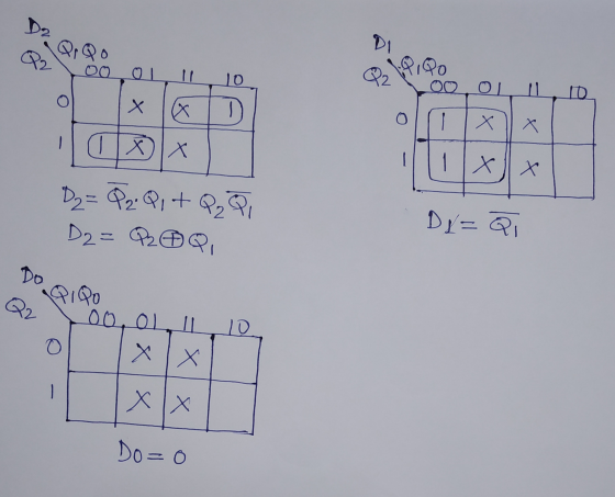
K Map Simplification -
Let D2, D1, D0 represent D inputs to D Flip Flop.
We will not use D0 as flip flop due to Q0 remains LOW throughout the count sequence.
Circuit Implementation

Add Answer to:
Question 3 40 pts Design a counter that starts at "0" and increases by two until...
Design a counter that starts at "0" and increases by two until you reach "6" and...
 Design a counter that starts at "0" and increases by two until you reach "6" and then starts at "0" again and continues counting in the same way. Your digital circuit design must be implemented using D-flipflops, and your answer must include: • The transition graph (be detailed and contain all proper directions and values) • The next state truth table (needs to include the present and next-state) • The K-map(s) for next-state equation • Determine the optimal SoP next...
Question 3 40 pts The owner of a store is about to do a grand reopening....
 Question 3 40 pts The owner of a store is about to do a grand reopening. She has purchased a "Welcome sign that lights up with different colors depending on the binary sequence it receives The entire sign lights up with a color, stays on with that color for a foved amount of time, then after the same fixed amount of time the sign shut off, then lights up with the next color for the same fixed amount of time,...
Question 5 20 pts Design a lighting system for a business sign that switches color after...
 Question 5 20 pts Design a lighting system for a business sign that switches color after a certain period of time from green to red to violet to blue and continues repeating in that order. You must show State Graph, Next State Table, then using a T flip flop fill in the proper Kmap, lastly show your circuit design all the including connection from the beginning all the way to the output to the lights
Question 5 20 pts Design...
Question 5 20 pts Design a lighting system for a business sign that switches color after a certain period of time from green to red to violet to blue and continues repeating in that order. You must show State Graph, Next State Table, then using a T flip flop fill in the proper Kmap, lastly show your circuit design all the including connection from the beginning all the way to the output to the lights
Question 5 20 pts Design...
1) Design a synchronous 3-bit binary UP/DOWN counter uses the following counting pattern 10.2.3.7.6.40.1.3...) the counter...
 1) Design a synchronous 3-bit binary UP/DOWN counter uses the following counting pattern 10.2.3.7.6.40.1.3...) the counter will count in this pattern indefinitely when the input X is equal to 1. When the input the counter will reverse direction and count in the opposite pattern 0. 4 7310) Complete the state diagram, transition table, New state s and solve for the recitation equations for flipflops that will perform this function. (You do not need to draw the flip-flops Use the state...
Using S-R flip-flops, design a 3-bit counter (C,B,A) with the repeating binary counting sequence: 1, 3,...
Using S-R flip-flops, design a 3-bit counter (C,B,A) with the repeating binary counting sequence: 1, 3, 2, 6, 7, 5, 4. - Show the circuit's state table with the present-state entries in ascending order, which should have the present state (t), next state (t+1), and flip-flop inputs. - Find the flip-flop input equations for RC, RB, and RA in Product of Sums form.
Design a 3-bit down counter FSM with no inputs and three outputs. Do this using a...
Design a 3-bit down counter FSM with no inputs and three outputs. Do this using a T flip flop. a. Draw a state diagram and the corresponding state table. b. Derive the equations for output functions and flip-flop input functions c. Draw the logic circuit diagram
Given the State Table Below 01* 02 03 1 203 X-1 0 000 01 0 0 0 1 0 0 A. Draw a state Diagram (5 points) B. Create the "design truth table" for the "next state" and the "output"...
 Given the State Table Below 01* 02 03 1 203 X-1 0 000 01 0 0 0 1 0 0 A. Draw a state Diagram (5 points) B. Create the "design truth table" for the "next state" and the "output" (5 points) C. Make a Karnaugh for each "next state" and the "output" (10 points) When making the Karnaugh maps, "xO1" should be along the top and "0203'" along the side (The two missing states should be considered "DONT CARES")...
Use S-R flip-flops to design a 3-bit counter (C, B, A) with the repeating binary counting...
 Use S-R flip-flops to design a 3-bit counter (C, B, A) with the repeating binary counting sequence: 1, 3, 2, 6, 7, 5, 4. Show clearly the following: (a) The circuit's state table with the present-state entries in ascending order. Present State (t) Next State (t+1) Flip-flop Inputs с B A m с B A Sc Rc SB RE SA RA Required format of the state table in Problem 1(a). Show table grid lines and align all entries per column....
Circuit : Custom up/down counter P3. Count Sequence Generate a random sequence of 8 distinct...
Circuit : Custom up/down counter P3. Count Sequence Generate a random sequence of 8 distinct numbers between 0 and 7. Start at any number, and not “in order”,13576420 Document your count sequence in the Lab Notebook. P4. State Diagram Create an FSM state diagram to cycle through your count sequence. Implement forward and backward counting, based on X (1 = forward, 0 = backward). Include a diagram. Create it with software or very neatly...
Please work on Part E & F Given the State Table Below Q1 Q2 Q3 X-1 X-0 X-1 10111loloi A. Draw a state Diagram (5 points) B. Create the "design truth table" for the "next state" an...
 Please work on Part E & F
Given the State Table Below Q1 Q2 Q3 X-1 X-0 X-1 10111loloi A. Draw a state Diagram (5 points) B. Create the "design truth table" for the "next state" and the "output"' (5 points) C. Make a Karnaugh for each "next state" and the "output" (10 points) When making the Karnaugh maps, "xQ1" should be along the top and "0203" along the side (The two missing states should be considered "DONT CARES") Write...
Please work on Part E & F
Given the State Table Below Q1 Q2 Q3 X-1 X-0 X-1 10111loloi A. Draw a state Diagram (5 points) B. Create the "design truth table" for the "next state" and the "output"' (5 points) C. Make a Karnaugh for each "next state" and the "output" (10 points) When making the Karnaugh maps, "xQ1" should be along the top and "0203" along the side (The two missing states should be considered "DONT CARES") Write...
 Design a counter that starts at "0" and increases by two until you reach "6" and then starts at "0" again and continues counting in the same way. Your digital circuit design must be implemented using D-flipflops, and your answer must include: • The transition graph (be detailed and contain all proper directions and values) • The next state truth table (needs to include the present and next-state) • The K-map(s) for next-state equation • Determine the optimal SoP next...
 Question 3 40 pts The owner of a store is about to do a grand reopening. She has purchased a "Welcome sign that lights up with different colors depending on the binary sequence it receives The entire sign lights up with a color, stays on with that color for a foved amount of time, then after the same fixed amount of time the sign shut off, then lights up with the next color for the same fixed amount of time,...
 Question 5 20 pts Design a lighting system for a business sign that switches color after a certain period of time from green to red to violet to blue and continues repeating in that order. You must show State Graph, Next State Table, then using a T flip flop fill in the proper Kmap, lastly show your circuit design all the including connection from the beginning all the way to the output to the lights
Question 5 20 pts Design...
Question 5 20 pts Design a lighting system for a business sign that switches color after a certain period of time from green to red to violet to blue and continues repeating in that order. You must show State Graph, Next State Table, then using a T flip flop fill in the proper Kmap, lastly show your circuit design all the including connection from the beginning all the way to the output to the lights
Question 5 20 pts Design...
 1) Design a synchronous 3-bit binary UP/DOWN counter uses the following counting pattern 10.2.3.7.6.40.1.3...) the counter will count in this pattern indefinitely when the input X is equal to 1. When the input the counter will reverse direction and count in the opposite pattern 0. 4 7310) Complete the state diagram, transition table, New state s and solve for the recitation equations for flipflops that will perform this function. (You do not need to draw the flip-flops Use the state...
 Given the State Table Below 01* 02 03 1 203 X-1 0 000 01 0 0 0 1 0 0 A. Draw a state Diagram (5 points) B. Create the "design truth table" for the "next state" and the "output" (5 points) C. Make a Karnaugh for each "next state" and the "output" (10 points) When making the Karnaugh maps, "xO1" should be along the top and "0203'" along the side (The two missing states should be considered "DONT CARES")...
 Use S-R flip-flops to design a 3-bit counter (C, B, A) with the repeating binary counting sequence: 1, 3, 2, 6, 7, 5, 4. Show clearly the following: (a) The circuit's state table with the present-state entries in ascending order. Present State (t) Next State (t+1) Flip-flop Inputs с B A m с B A Sc Rc SB RE SA RA Required format of the state table in Problem 1(a). Show table grid lines and align all entries per column....
 Please work on Part E & F
Given the State Table Below Q1 Q2 Q3 X-1 X-0 X-1 10111loloi A. Draw a state Diagram (5 points) B. Create the "design truth table" for the "next state" and the "output"' (5 points) C. Make a Karnaugh for each "next state" and the "output" (10 points) When making the Karnaugh maps, "xQ1" should be along the top and "0203" along the side (The two missing states should be considered "DONT CARES") Write...
Please work on Part E & F
Given the State Table Below Q1 Q2 Q3 X-1 X-0 X-1 10111loloi A. Draw a state Diagram (5 points) B. Create the "design truth table" for the "next state" and the "output"' (5 points) C. Make a Karnaugh for each "next state" and the "output" (10 points) When making the Karnaugh maps, "xQ1" should be along the top and "0203" along the side (The two missing states should be considered "DONT CARES") Write...
Most questions answered within 3 hours.
-
New Air Heating and Cooling, manufactures furnaces and central
air units. The company pride itself on...
asked 3 seconds from now -
A coach uses a new technique to train gymnasts. Seven
gymnasts were randomly selected and their...
asked 1 hour ago -
While rotating the tires on your car you notice a rock [mass =
0.1 Kg] stuck...
asked 3 hours ago -
Using MARS simulator, write MIPS programs according to
the following scenarios: Receive a positive integer number...
asked 5 hours ago -
An object in front of a concave mirror has a real image that is
11.5 cm...
asked 6 hours ago -
Consider the reaction, C3 H8 + O2 --> CO2 + H2O. How many
moles of O2...
asked 7 hours ago -
You and your opponent both roll a fair die. If you both roll the
same number,...
asked 8 hours ago -
In a study of the accuracy of fast food drive-through orders,
Restaurant A had 257 accurate...
asked 8 hours ago -
Identify and describe in detail the four categories of
institutions that could be included in a...
asked 8 hours ago -
In python
class Customer:
def __init__(self, customer_id, last_name, first_name, phone_number, address):
self._customer_id = int(customer_id)
self._last_name =...
asked 8 hours ago -
What is an example of a limitation in implementing a new
ERP system and how it...
asked 8 hours ago -
In a section of 9.7cm of an artery with a radius of 2.6mm there
is a...
asked 8 hours ago