
Homework Answers
Add Answer to:
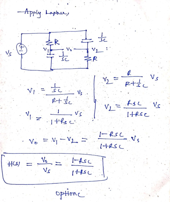
For the phase shifter circuit shown below, find H(s) = V.Ns. R с + + V....
Find the transfer function H(jω) for the circuit above as a function of jω. (Leave R...
 Find the transfer function H(jω) for the
circuit above as a function of jω. (Leave R and L as variables).
Assume V R to be the output and V S to be the input.
С L RVR(t) vs (t) A. Find the transfer function H(jo) for the circuit above as a function of jaw. (Leave R and L as variables). Assume V to be the output and V to be the input. S R B. Find the Magnitude and Phase...
Find the transfer function H(jω) for the
circuit above as a function of jω. (Leave R and L as variables).
Assume V R to be the output and V S to be the input.
С L RVR(t) vs (t) A. Find the transfer function H(jo) for the circuit above as a function of jaw. (Leave R and L as variables). Assume V to be the output and V to be the input. S R B. Find the Magnitude and Phase...
Electrical engineering problem 1251 Problem 2 For the circuit below a) Convert input V.lt) into Amplitude and phase form b) Find the output response V(t) using Fourier series in the circuit shown, dra...
 Electrical engineering problem
1251 Problem 2 For the circuit below a) Convert input V.lt) into Amplitude and phase form b) Find the output response V(t) using Fourier series in the circuit shown, draw frequency spectrum (only amplityde) for until four non zero terms o v(t) 5Ω 1 H 100 mF
1251 Problem 2 For the circuit below a) Convert input V.lt) into Amplitude and phase form b) Find the output response V(t) using Fourier series in the circuit shown, draw...
Electrical engineering problem
1251 Problem 2 For the circuit below a) Convert input V.lt) into Amplitude and phase form b) Find the output response V(t) using Fourier series in the circuit shown, draw frequency spectrum (only amplityde) for until four non zero terms o v(t) 5Ω 1 H 100 mF
1251 Problem 2 For the circuit below a) Convert input V.lt) into Amplitude and phase form b) Find the output response V(t) using Fourier series in the circuit shown, draw...
T1.4. The circuit shown in Figure T1.4 has Vs = 12 V, v 2 =4 V,...
 T1.4. The circuit shown in Figure T1.4 has Vs = 12 V, v 2 =4 V, and R 1 =42 Figure T1.4 a. Find the values of a. v1; b. i c. R2 T1.5. We are given Vs =15 V, R=10 , and a= 0.3 S for the circuit of Figure T1.5. Find the value of the current i sc flowing through the short circuit. o ar, a=0.35 Figure T1.5
The circuit shown below has the impedance Z(s) = 800(s +1) (s+ 1 +j50) (s +1...
 The circuit shown below has the impedance Z(s) = 800(s +1) (s+ 1 +j50) (s +1 -j50) , S = - jo. R с L Z(s) References eBook & Resources Section Break Difficulty: Medium value: 10.00 points Find the values of R, L, C, and G. The value of R in the circuit is 12. The value of L in the circuit is H. The value of C in the circuit is mF. The value of G in the circuit...
(1 point) In the circuit shown below, if R = 1212, ZL = j1512, ZC =...
 (1 point) In the circuit shown below, if R = 1212, ZL = j1512, ZC = -31012, find the complex power for each element. Vs 120+ jo v $. $ $ Sc Svin =
the circuit shown, 1. Find the transfer function H(jw) 2. If R R2 12 and L1mH, plot the frequency response (both the ga...
 the circuit shown, 1. Find the transfer function H(jw) 2. If R R2 12 and L1mH, plot the frequency response (both the gain and the phase shift) of the circuit; 3. Identify the type of filter the circuit is, and state the break (cut off) frequency. R1 v(t)Vcos(ut) L1 R2 Figure 1
the circuit shown, 1. Find the transfer function H(jw) 2. If R R2 12 and L1mH, plot the frequency response (both the gain and the phase shift) of...
the circuit shown, 1. Find the transfer function H(jw) 2. If R R2 12 and L1mH, plot the frequency response (both the gain and the phase shift) of the circuit; 3. Identify the type of filter the circuit is, and state the break (cut off) frequency. R1 v(t)Vcos(ut) L1 R2 Figure 1
the circuit shown, 1. Find the transfer function H(jw) 2. If R R2 12 and L1mH, plot the frequency response (both the gain and the phase shift) of...
4. In the circuit shown, R - 500 ohm, L -0.64 H, C - 1u F, 1- -1 A, Vcap (o) -40 v, indur (o ) - ...
 4. In the circuit shown, R - 500 ohm, L -0.64 H, C - 1u F, 1- -1 A, Vcap (o) -40 v, indur (o ) - 0.5 A. Find a. IR (o) b. Derive a differential equation for current Derive an expression for the v(t) c. C 3
4. In the circuit shown, R - 500 ohm, L -0.64 H, C - 1u F, 1- -1 A, Vcap (o) -40 v, indur (o ) - 0.5 A. Find a....
4. In the circuit shown, R - 500 ohm, L -0.64 H, C - 1u F, 1- -1 A, Vcap (o) -40 v, indur (o ) - 0.5 A. Find a. IR (o) b. Derive a differential equation for current Derive an expression for the v(t) c. C 3
4. In the circuit shown, R - 500 ohm, L -0.64 H, C - 1u F, 1- -1 A, Vcap (o) -40 v, indur (o ) - 0.5 A. Find a....
Question 4. Refer to the circuit of Figure 4. R 802 50 uF с vi(t) v.(t)...
 Question 4. Refer to the circuit of Figure 4. R 802 50 uF с vi(t) v.(t) Figure 4 a) Draw the circuit in the Laplace domain, and then apply basic circuit theory in the Laplace domain to show that the Laplace transfer function H(s) defined for this system is: HS) V.(5) V (5) sta where a= RC [8 Marks] b) Use Laplace methods to determine the output voltage vo(t) when the input voltage is defined as: v (1) 40(1) The...
In the circuit shown in the figure below, let L = 4.70 H, R = 4.20...
 In the circuit shown in the figure below, let L = 4.70 H, R = 4.20 s, and ε = 120 V. What is the self-induced emf 0.200 s after the switch is closed? 225.6 * V What is the equation for the current as a function of time in this circuit? R Need Help? Read It Watch It
Q1) Find the equivalent impedance of the circuit below in the S-domain. UC2F 30.5 H is(t)...
 Q1) Find the equivalent impedance of the circuit below in the S-domain. UC2F 30.5 H is(t) Q2) The circuit of shown below, Given that R-422, L=2H and i (0-) = 1 A. The current source in the circuit is given as is(t) = 3e 'u(t) A. a) Considering the initial conditions, redraw the circuit in the s-domain. b) Identify which circuit analysis approach could be used to solve this problem. c) Formulate the problem by writing the equations that describe...
 Find the transfer function H(jω) for the
circuit above as a function of jω. (Leave R and L as variables).
Assume V R to be the output and V S to be the input.
С L RVR(t) vs (t) A. Find the transfer function H(jo) for the circuit above as a function of jaw. (Leave R and L as variables). Assume V to be the output and V to be the input. S R B. Find the Magnitude and Phase...
Find the transfer function H(jω) for the
circuit above as a function of jω. (Leave R and L as variables).
Assume V R to be the output and V S to be the input.
С L RVR(t) vs (t) A. Find the transfer function H(jo) for the circuit above as a function of jaw. (Leave R and L as variables). Assume V to be the output and V to be the input. S R B. Find the Magnitude and Phase...
 Electrical engineering problem
1251 Problem 2 For the circuit below a) Convert input V.lt) into Amplitude and phase form b) Find the output response V(t) using Fourier series in the circuit shown, draw frequency spectrum (only amplityde) for until four non zero terms o v(t) 5Ω 1 H 100 mF
1251 Problem 2 For the circuit below a) Convert input V.lt) into Amplitude and phase form b) Find the output response V(t) using Fourier series in the circuit shown, draw...
Electrical engineering problem
1251 Problem 2 For the circuit below a) Convert input V.lt) into Amplitude and phase form b) Find the output response V(t) using Fourier series in the circuit shown, draw frequency spectrum (only amplityde) for until four non zero terms o v(t) 5Ω 1 H 100 mF
1251 Problem 2 For the circuit below a) Convert input V.lt) into Amplitude and phase form b) Find the output response V(t) using Fourier series in the circuit shown, draw...
 T1.4. The circuit shown in Figure T1.4 has Vs = 12 V, v 2 =4 V, and R 1 =42 Figure T1.4 a. Find the values of a. v1; b. i c. R2 T1.5. We are given Vs =15 V, R=10 , and a= 0.3 S for the circuit of Figure T1.5. Find the value of the current i sc flowing through the short circuit. o ar, a=0.35 Figure T1.5
 The circuit shown below has the impedance Z(s) = 800(s +1) (s+ 1 +j50) (s +1 -j50) , S = - jo. R с L Z(s) References eBook & Resources Section Break Difficulty: Medium value: 10.00 points Find the values of R, L, C, and G. The value of R in the circuit is 12. The value of L in the circuit is H. The value of C in the circuit is mF. The value of G in the circuit...
 (1 point) In the circuit shown below, if R = 1212, ZL = j1512, ZC = -31012, find the complex power for each element. Vs 120+ jo v $. $ $ Sc Svin =
 the circuit shown, 1. Find the transfer function H(jw) 2. If R R2 12 and L1mH, plot the frequency response (both the gain and the phase shift) of the circuit; 3. Identify the type of filter the circuit is, and state the break (cut off) frequency. R1 v(t)Vcos(ut) L1 R2 Figure 1
the circuit shown, 1. Find the transfer function H(jw) 2. If R R2 12 and L1mH, plot the frequency response (both the gain and the phase shift) of...
the circuit shown, 1. Find the transfer function H(jw) 2. If R R2 12 and L1mH, plot the frequency response (both the gain and the phase shift) of the circuit; 3. Identify the type of filter the circuit is, and state the break (cut off) frequency. R1 v(t)Vcos(ut) L1 R2 Figure 1
the circuit shown, 1. Find the transfer function H(jw) 2. If R R2 12 and L1mH, plot the frequency response (both the gain and the phase shift) of...
 4. In the circuit shown, R - 500 ohm, L -0.64 H, C - 1u F, 1- -1 A, Vcap (o) -40 v, indur (o ) - 0.5 A. Find a. IR (o) b. Derive a differential equation for current Derive an expression for the v(t) c. C 3
4. In the circuit shown, R - 500 ohm, L -0.64 H, C - 1u F, 1- -1 A, Vcap (o) -40 v, indur (o ) - 0.5 A. Find a....
4. In the circuit shown, R - 500 ohm, L -0.64 H, C - 1u F, 1- -1 A, Vcap (o) -40 v, indur (o ) - 0.5 A. Find a. IR (o) b. Derive a differential equation for current Derive an expression for the v(t) c. C 3
4. In the circuit shown, R - 500 ohm, L -0.64 H, C - 1u F, 1- -1 A, Vcap (o) -40 v, indur (o ) - 0.5 A. Find a....
 Question 4. Refer to the circuit of Figure 4. R 802 50 uF с vi(t) v.(t) Figure 4 a) Draw the circuit in the Laplace domain, and then apply basic circuit theory in the Laplace domain to show that the Laplace transfer function H(s) defined for this system is: HS) V.(5) V (5) sta where a= RC [8 Marks] b) Use Laplace methods to determine the output voltage vo(t) when the input voltage is defined as: v (1) 40(1) The...
 In the circuit shown in the figure below, let L = 4.70 H, R = 4.20 s, and ε = 120 V. What is the self-induced emf 0.200 s after the switch is closed? 225.6 * V What is the equation for the current as a function of time in this circuit? R Need Help? Read It Watch It
 Q1) Find the equivalent impedance of the circuit below in the S-domain. UC2F 30.5 H is(t) Q2) The circuit of shown below, Given that R-422, L=2H and i (0-) = 1 A. The current source in the circuit is given as is(t) = 3e 'u(t) A. a) Considering the initial conditions, redraw the circuit in the s-domain. b) Identify which circuit analysis approach could be used to solve this problem. c) Formulate the problem by writing the equations that describe...
Most questions answered within 3 hours.
-
In
IUPAC naming, do we concider the prefix in alphabatizing?
In other words do we look...
asked 1 minute ago -
If a trust has income required to be distributed of $11,500,
other amounts paid or required...
asked 17 minutes ago -
The degree of ionization of a weak acid
____________________.
Select all that are True.
a) varies...
asked 17 minutes ago -
Cereal for Breakfast. A cereal company claims
70% of Americans start the day with cereal for...
asked 18 minutes ago -
An elevator has a placard stating that the maximum capacity is
2400 lblong dash15 passengers. So,...
asked 21 minutes ago -
two charged proteins P1 and P2 are located at the positions
(1m,1m) and (-1m,1m) respectively on...
asked 31 minutes ago -
eBook
Calculator
Job Order Cost Sheet
Remnant Carpet Company sells and installs commercial carpeting
for office...
asked 36 minutes ago -
Using Kapustinskii equation, determine the lattice energy of a
hypothetical compound NaCl2 . Assume the sum...
asked 38 minutes ago -
Most schools and
businesses require some standard style of documentation for written
reports. Discuss why might...
asked 36 minutes ago -
cookbooks are going metric. in such books 1 cup is equal to 240
ml. Express 1...
asked 39 minutes ago -
________40. Which of the following is the correct sequence of
steps in the general
adaptation...
asked 47 minutes ago -
Hi, Please draw the network diagram.
Activity D on a CPM network has predecessors B and...
asked 49 minutes ago