
Homework Answers


Add Answer to:
The 25 foot beam is loaded as shown below. a. (10 points) Draw the shear and...
2. (10 points) Consider the beam shown below: (a) draw the complete shear diagram with corresponding...
 2. (10 points) Consider the beam shown below: (a) draw the complete shear diagram with corresponding labels and units (b) draw the complete moment diagram with corresponding labels and units (c) find the magnitude of maximum compressive normal stress (d) find the magnitude of the maximum tensile normal stress Give the value and location for all quantities along the beam and on the cross section. NOTE: The moment of inertia is I, = 99.75 in* and the centroid is given....
2. (10 points) Consider the beam shown below: (a) draw the complete shear diagram with corresponding...
 2. (10 points) Consider the beam shown below: (a) draw the complete shear diagram with corresponding labels and units (b) draw the complete moment diagram with corresponding labels and units (c) find the magnitude of maximum compressive normal stress (d) find the magnitude of the maximum tensile normal stress Give the value and location for all quantities along the beam and on the cross section. NOTE: The moment of inertia is 12 = 99.75 in4 and the centroid is given....
Blem 2. (70 points) 1. For the beam shown in Figure (a): a) b) draw the shear force and bending m...
 blem 2. (70 points) 1. For the beam shown in Figure (a): a) b) draw the shear force and bending moment diagrams. (30 points) Select the most economical W shape for the beam with an allowable bending stress of 30 ksi. (10 points) determine the maximum tensile and compressive bending stresses at any location along the beam if the section shown in Figure (b) is used instead of the W shape section selectedin Part b. Would the beam be safe...
A beam having a T-Section is loaded as shown in figure below.
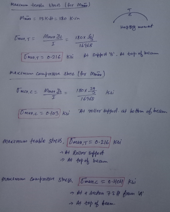
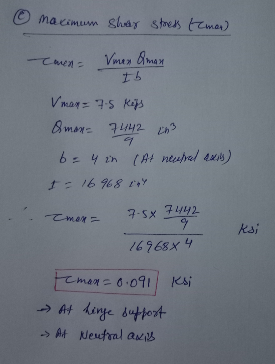
 A beam having a T-Section is loaded as shown in figure below. a. Draw the Shear Force & Bending Moment Diagram b. Locate the Nuetral Axis c. Find the maximum tensile and compressive bending stress d. Find the maximum shear stress e Find the Bending Stress and Shear Stress at the points marked on the cross section
2. Draw Shear Force and Bending Moment Diagram (use your preferred method). Determine Maximum Ten...
 2. Draw Shear Force and Bending Moment Diagram (use your preferred method). Determine Maximum Tensile and Compressive Stresses due to bending, state where on the beam these occur. For the mid-point between A and B, determine shear stress at neutral axis; 2" from the top of the flange; at the junction between web and flange and on the top of the flange for the cross-section. Plot of the bending stress and shear stress distribution diagram across the cross section of...
Q3 (25 pts) 3. For the cantilever beam shown below and to the left, Determine the...
 Q3
(25 pts) 3. For the cantilever beam shown below and to the left, Determine the reactions at the wall at C. Draw the shear (V) and moment (M) diagram for the beam and label the appropriate values. For the given cross section, determine the magnitude of the maximum COMPRESSIVE bending stress and state where this occurs along the length of the beam and along the height of the beam (top or bottom). Sketch the NORMAL stress distribution (profile) for...
Q3
(25 pts) 3. For the cantilever beam shown below and to the left, Determine the reactions at the wall at C. Draw the shear (V) and moment (M) diagram for the beam and label the appropriate values. For the given cross section, determine the magnitude of the maximum COMPRESSIVE bending stress and state where this occurs along the length of the beam and along the height of the beam (top or bottom). Sketch the NORMAL stress distribution (profile) for...
(a) draw the complete shear diagram with corresponding labels and units (b) draw the complete moment...
 (a) draw the complete shear diagram with corresponding labels and units (b) draw the complete moment diagram with corresponding labels and units (c) find the magnitude of maximum compressive normal stress (d) find the magnitude of the maximum tensile normal stress Give the value and location for all quantities along the beam and on the cross section. NOTE: The moment of inertia is I = 99.75 in and the centroid is given. Clearly label all significant quantities in your shear...
Problem 1: Draw the shear force and bending moment diagram for the beam shown below. (10)...
 Problem 1: Draw the shear force and bending moment diagram for the beam shown below. (10) Estimate the maximum bending stress located at section C (shown below). (10) Clearly identify the location on the cross section where the maximum bending stress is located. Is it tensile or compressive? Explain your answer.
Question 1 1. A steel beam is loaded as shown complete the following a. Draw a...
 Question 1 1. A steel beam is loaded as shown complete the following a. Draw a neat shear force and bending moment diagrams using area moment method b. Determine the maximum bending stress, clearly indication where this occurs c. Determine the maximum shear stress clearly indication where this occurs d, Plot the bending and shear stress for the cross section at x = 5 ft. from the left hand support e. Using area moment method, determine the deflection at the...
 2. (10 points) Consider the beam shown below: (a) draw the complete shear diagram with corresponding labels and units (b) draw the complete moment diagram with corresponding labels and units (c) find the magnitude of maximum compressive normal stress (d) find the magnitude of the maximum tensile normal stress Give the value and location for all quantities along the beam and on the cross section. NOTE: The moment of inertia is I, = 99.75 in* and the centroid is given....
 2. (10 points) Consider the beam shown below: (a) draw the complete shear diagram with corresponding labels and units (b) draw the complete moment diagram with corresponding labels and units (c) find the magnitude of maximum compressive normal stress (d) find the magnitude of the maximum tensile normal stress Give the value and location for all quantities along the beam and on the cross section. NOTE: The moment of inertia is I, = 99.75 in* and the centroid is given....
 2. (10 points) Consider the beam shown below: (a) draw the complete shear diagram with corresponding labels and units (b) draw the complete moment diagram with corresponding labels and units (c) find the magnitude of maximum compressive normal stress (d) find the magnitude of the maximum tensile normal stress Give the value and location for all quantities along the beam and on the cross section. NOTE: The moment of inertia is 12 = 99.75 in4 and the centroid is given....
 blem 2. (70 points) 1. For the beam shown in Figure (a): a) b) draw the shear force and bending moment diagrams. (30 points) Select the most economical W shape for the beam with an allowable bending stress of 30 ksi. (10 points) determine the maximum tensile and compressive bending stresses at any location along the beam if the section shown in Figure (b) is used instead of the W shape section selectedin Part b. Would the beam be safe...
 2. Draw Shear Force and Bending Moment Diagram (use your preferred method). Determine Maximum Tensile and Compressive Stresses due to bending, state where on the beam these occur. For the mid-point between A and B, determine shear stress at neutral axis; 2" from the top of the flange; at the junction between web and flange and on the top of the flange for the cross-section. Plot of the bending stress and shear stress distribution diagram across the cross section of...
 Q3
(25 pts) 3. For the cantilever beam shown below and to the left, Determine the reactions at the wall at C. Draw the shear (V) and moment (M) diagram for the beam and label the appropriate values. For the given cross section, determine the magnitude of the maximum COMPRESSIVE bending stress and state where this occurs along the length of the beam and along the height of the beam (top or bottom). Sketch the NORMAL stress distribution (profile) for...
Q3
(25 pts) 3. For the cantilever beam shown below and to the left, Determine the reactions at the wall at C. Draw the shear (V) and moment (M) diagram for the beam and label the appropriate values. For the given cross section, determine the magnitude of the maximum COMPRESSIVE bending stress and state where this occurs along the length of the beam and along the height of the beam (top or bottom). Sketch the NORMAL stress distribution (profile) for...
 (a) draw the complete shear diagram with corresponding labels and units (b) draw the complete moment diagram with corresponding labels and units (c) find the magnitude of maximum compressive normal stress (d) find the magnitude of the maximum tensile normal stress Give the value and location for all quantities along the beam and on the cross section. NOTE: The moment of inertia is I = 99.75 in and the centroid is given. Clearly label all significant quantities in your shear...
 Problem 1: Draw the shear force and bending moment diagram for the beam shown below. (10) Estimate the maximum bending stress located at section C (shown below). (10) Clearly identify the location on the cross section where the maximum bending stress is located. Is it tensile or compressive? Explain your answer.
 Question 1 1. A steel beam is loaded as shown complete the following a. Draw a neat shear force and bending moment diagrams using area moment method b. Determine the maximum bending stress, clearly indication where this occurs c. Determine the maximum shear stress clearly indication where this occurs d, Plot the bending and shear stress for the cross section at x = 5 ft. from the left hand support e. Using area moment method, determine the deflection at the...
Most questions answered within 3 hours.
-
Under all the various types of market structures, firms
must eventually earn some economic profits for...
asked 51 seconds from now -
Consider the following fitness regime for a single locus trait
with two co-dominant alleles: w11 =...
asked 3 minutes ago -
A large cable company reports the following.
80% of its customers subscribe to its cable TV...
asked 19 minutes ago -
Please answer the question in brief.
Discuss the role of ERP in organizations. Are ERP tools...
asked 5 minutes ago -
Discuss the pros and cons of collaborative software such
as SameTime. Does it increase productivity? What...
asked 17 minutes ago -
1. Are all good samples random?
2. Magazines often report surveys giving statistics such as “63%...
asked 12 minutes ago -
Buying your in-laws a gift because it’s expected is
due to the ____________ motive of gift-giving....
asked 20 minutes ago -
Calculate the expected value, the variance, and the standard
deviation of the given random variable X....
asked 1 hour ago -
A hospital performs 100 surgeries per week. The probability that
complications after surgery occur is 10%....
asked 1 hour ago -
1 point) Given the significance level α=0.01 find the following:
(a) left-tailed z value z= (b)...
asked 1 hour ago -
Assuming you are the head of the software development unit at
Cyber.Soft, explain and justify why...
asked 27 minutes ago -
Magnesium and nitrogen react in a combination reaction to
produce magnesium nitride. 3 Mg + N2...
asked 35 minutes ago