Apply the following questions to both the circuit shown in Figure (a) (resistors in series) and...
Apply the following questions to both the circuit shown in
Figure (a) (resistors in series) and the circuit shown in Figure
(b) (resistors in parallel).
(a) Use Ohm's law with Kirchhoff's current and voltage laws to
derive equations for currents i1, i2 and
i (through Resistor R1, resistor R2, and
the voltage source , respectively) in terms of R1,
R2, and v.
(b) R1 and R2 can be interchanged with an equivalent resistor rith resistance R without changing the values of v and i. Show the derivation of an equation for the equivalent resistance R in terms of R1 and R2.


(a) (b)
Homework Answers
Ans

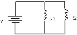
fig a fig b
A) let us assume that current i , i1 and i2 is flowing through voltage source v , the resistor r1 and r2 respectively in fig a and b respectively.
In fig a i1=i2=i
using kvl in fig a
V=i1*R1+i2*R2=i(R1+R2)..........................................................1
hence, i=i1=i2=V/(R1+R2)
in fig b
i=i1+i2
v=i1*R1=i2*R2=(i-i1)*R2........................................................2
i1*R1+i1*R2=i*R2
hence,i1=i*R2/(R1+R2)
v=i*R1*R2/(R1+R2).......................................................................3
i=v*(R1+R2)/R2*R1
i1=v/R1 (from eq. 2)
i2=v/R2 (from eq. 2)
B) We knoe that V=I*R
from the equation 1 it is clear that
Equivalent resistor R=R1+R2 (in series)
from equation 3 it is clear that
Equivalent Resistor R=R1*R2/(R1+R2) (in parallel)


B).
We knoe that V=IR
from the equation 1 it is clear that
Equivalent resistor R=r1+r2 (in series)
from equation 3 it is clear that
Equivalent Resistor R=r1*r2/(r1+r2) (in parallel)
Add Answer to:
Apply the following questions to both the circuit shown in
Figure (a) (resistors in series) and...
Consider the circuit shown in the figure(Figure 1). Suppose thefour resistors in this circuit have...
 Consider the circuit shown in the figure(Figure 1). Suppose the
four resistors in this circuit have the values R1 = 13 Ω , R2 = 7.2
Ω , R3 = 6.2 Ω , and R4= 13 Ω , and that the emf of the battery is
E = 18 V .Part AFind the current through each resistor using the rules for
series and parallel resistors. Express your answers using two
significant figures separated by commas.I1,I2,I3,I4=______APart BFind the current through each...
Consider the circuit shown in the figure(Figure 1). Suppose the
four resistors in this circuit have the values R1 = 13 Ω , R2 = 7.2
Ω , R3 = 6.2 Ω , and R4= 13 Ω , and that the emf of the battery is
E = 18 V .Part AFind the current through each resistor using the rules for
series and parallel resistors. Express your answers using two
significant figures separated by commas.I1,I2,I3,I4=______APart BFind the current through each...
Pre-lab EM-5 Ohm's Law and Kirchhoff's Rules Ohm's Law The resistance R of a device can...
 Pre-lab EM-5 Ohm's Law and Kirchhoff's Rules Ohm's Law The resistance R of a device can be determined by either directly measuring the resistance using an ohmmeter, or by measuring the current I through it and the voltage Vacross it, and then calculating R using Ohm's Law V R= (1) If the voltage across a resistor is 10V, and the current passing through it is 2.5 mA. of the resistor? What is the resistance R= Ω. Kirchhoffs Loop Rule Around...
Learning Goal: To learn to calculate the equivalent resistance of the circuits combining series and parallel...
 Learning Goal:
To learn to calculate the equivalent resistance of the circuits
combining series and parallel connections.
Resistors are often connected to each other in electric
circuits. Finding the equivalent resistanceof
combinations of resistors is a common and important task.
Equivalent resistance is defined as the single resistance that can
replace the given combination of resistors in such a manner that
the currents in the rest of the circuit do not change.
Finding the equivalent resistance is relatively straighforward if...
Learning Goal:
To learn to calculate the equivalent resistance of the circuits
combining series and parallel connections.
Resistors are often connected to each other in electric
circuits. Finding the equivalent resistanceof
combinations of resistors is a common and important task.
Equivalent resistance is defined as the single resistance that can
replace the given combination of resistors in such a manner that
the currents in the rest of the circuit do not change.
Finding the equivalent resistance is relatively straighforward if...
Review Part A Consider the circuit shown in the figure(Figure 1). Suppose the four resistors in...
 Review Part A Consider the circuit shown in the figure(Figure 1). Suppose the four resistors in this circuit have the values R1-10 Ω , R2- 7.2 Ω , R3 6.4 Ω , and R-12 Ω , and that the emf of the battery is E- 18 V Find the current through each resistor using the rules for series and parallel resistors Express your answers using two significant figures separated by commas. 11,12,13,14 = Submit Figure of 1 Part B Find...
Consider the circuit shown in (Figure 1) , where all resistors have the same resistance R....
 Consider the circuit shown in
(Figure
1)
, where all resistors have the same resistance R.
At
t=0,
with the capacitor C
uncharged, the switch is closed.At
t=0,
the three currents can be determined by analyzing a simpler, but
equivalent, circuit. Identify this simpler circuit and use it to
find the values of
I1
,
I2,
and
I3
at
t=0.
Consider the circuit shown in (Figure 1) , where all resistors have the same resistance R. At t=0, with the...
Consider the circuit shown in
(Figure
1)
, where all resistors have the same resistance R.
At
t=0,
with the capacitor C
uncharged, the switch is closed.At
t=0,
the three currents can be determined by analyzing a simpler, but
equivalent, circuit. Identify this simpler circuit and use it to
find the values of
I1
,
I2,
and
I3
at
t=0.
Consider the circuit shown in (Figure 1) , where all resistors have the same resistance R. At t=0, with the...
A four-resistor circuit is shown in the figure. The values of the resistors are as follows:...
 A four-resistor circuit is shown in the figure. The values of
the resistors are as follows: R1=4 Ohms,
R2=R3=R4=3 Ohms. What is the
equivalent resistance Req for this circuit?
R4 R1 R23 R₂ }
A four-resistor circuit is shown in the figure. The values of
the resistors are as follows: R1=4 Ohms,
R2=R3=R4=3 Ohms. What is the
equivalent resistance Req for this circuit?
R4 R1 R23 R₂ }
Consider the electric circuit shown in the figure. Assume that the voltage of the battery is...
 Consider the electric circuit shown in the figure. Assume that
the voltage of the battery is V = 23.5 V, and the resistors are
R1 = R2 = R3 = R4 =
R5 = 2.00 Ω.
What is the equivalent resistance of the circuit?
What is the electric current flowing through resistor
R3?
Consider the electri = R4 = R5 = 2.00 2 circuit shown in the figure. Assume that the voltage of the battery is V = 23.5 V,...
Consider the electric circuit shown in the figure. Assume that
the voltage of the battery is V = 23.5 V, and the resistors are
R1 = R2 = R3 = R4 =
R5 = 2.00 Ω.
What is the equivalent resistance of the circuit?
What is the electric current flowing through resistor
R3?
Consider the electri = R4 = R5 = 2.00 2 circuit shown in the figure. Assume that the voltage of the battery is V = 23.5 V,...
Three Resistors in Parallel Three resistors are connected in parallel as shown in figure (a). A...
 Three Resistors in Parallel Three resistors are connected in parallel as shown in figure (a). A potential difference of 12.0V is maintained between points a and b. Three resistors connected in parallel. The Another circuit with three resistors and a voltage across each resistor is 12.0 V. battery. Is it equivalent to the circuit in (a)? a Ž 3.00 6.00 9.00 3.00 6.00 09.00 (a) Calculate the equivalent resistance of the circuit. SOLUTION Conceptualize Figure (a) shows that we are...
3. Kirchhoff's Laws: In this experiment you will verify both Kirchhoff's laws. Consider the following circuit...
 3. Kirchhoff's Laws: In this experiment you will verify both Kirchhoff's laws. Consider the following circuit diagram. R1 10 kΩ 11 A I2 I3 +V1 -10 V R2 4.7 kΩ R3 8.2 kQ Figure 1.2 A. Consider figure 1.2. What is the equivalent resistance between D and C? B. What is the power provided by the voltage source? What is the power dissipated by the 8.2kQ resistor? C. Propose a method to measure the power in the lab (when you...
In the circuit shown in the figure. R1 = 15,00 Ohm, R2 = 10.0 Ohm, R3...
 In the circuit shown in the figure. R1 = 15,00 Ohm, R2 = 10.0 Ohm, R3 = 5.0 Ohm, V emf,1 = 15.0 V. and Vemf,2 = 10.0 V. Using Kirchhoff's Loop and Junction Rules, determine the currents i1, i2, and i3 flowing through R1, R2, and R3, respectively, in the direction indicated in the figure.
 Consider the circuit shown in the figure(Figure 1). Suppose the
four resistors in this circuit have the values R1 = 13 Ω , R2 = 7.2
Ω , R3 = 6.2 Ω , and R4= 13 Ω , and that the emf of the battery is
E = 18 V .Part AFind the current through each resistor using the rules for
series and parallel resistors. Express your answers using two
significant figures separated by commas.I1,I2,I3,I4=______APart BFind the current through each...
Consider the circuit shown in the figure(Figure 1). Suppose the
four resistors in this circuit have the values R1 = 13 Ω , R2 = 7.2
Ω , R3 = 6.2 Ω , and R4= 13 Ω , and that the emf of the battery is
E = 18 V .Part AFind the current through each resistor using the rules for
series and parallel resistors. Express your answers using two
significant figures separated by commas.I1,I2,I3,I4=______APart BFind the current through each...
 Pre-lab EM-5 Ohm's Law and Kirchhoff's Rules Ohm's Law The resistance R of a device can be determined by either directly measuring the resistance using an ohmmeter, or by measuring the current I through it and the voltage Vacross it, and then calculating R using Ohm's Law V R= (1) If the voltage across a resistor is 10V, and the current passing through it is 2.5 mA. of the resistor? What is the resistance R= Ω. Kirchhoffs Loop Rule Around...
 Learning Goal:
To learn to calculate the equivalent resistance of the circuits
combining series and parallel connections.
Resistors are often connected to each other in electric
circuits. Finding the equivalent resistanceof
combinations of resistors is a common and important task.
Equivalent resistance is defined as the single resistance that can
replace the given combination of resistors in such a manner that
the currents in the rest of the circuit do not change.
Finding the equivalent resistance is relatively straighforward if...
Learning Goal:
To learn to calculate the equivalent resistance of the circuits
combining series and parallel connections.
Resistors are often connected to each other in electric
circuits. Finding the equivalent resistanceof
combinations of resistors is a common and important task.
Equivalent resistance is defined as the single resistance that can
replace the given combination of resistors in such a manner that
the currents in the rest of the circuit do not change.
Finding the equivalent resistance is relatively straighforward if...
 Review Part A Consider the circuit shown in the figure(Figure 1). Suppose the four resistors in this circuit have the values R1-10 Ω , R2- 7.2 Ω , R3 6.4 Ω , and R-12 Ω , and that the emf of the battery is E- 18 V Find the current through each resistor using the rules for series and parallel resistors Express your answers using two significant figures separated by commas. 11,12,13,14 = Submit Figure of 1 Part B Find...
 Consider the circuit shown in
(Figure
1)
, where all resistors have the same resistance R.
At
t=0,
with the capacitor C
uncharged, the switch is closed.At
t=0,
the three currents can be determined by analyzing a simpler, but
equivalent, circuit. Identify this simpler circuit and use it to
find the values of
I1
,
I2,
and
I3
at
t=0.
Consider the circuit shown in (Figure 1) , where all resistors have the same resistance R. At t=0, with the...
Consider the circuit shown in
(Figure
1)
, where all resistors have the same resistance R.
At
t=0,
with the capacitor C
uncharged, the switch is closed.At
t=0,
the three currents can be determined by analyzing a simpler, but
equivalent, circuit. Identify this simpler circuit and use it to
find the values of
I1
,
I2,
and
I3
at
t=0.
Consider the circuit shown in (Figure 1) , where all resistors have the same resistance R. At t=0, with the...
 A four-resistor circuit is shown in the figure. The values of
the resistors are as follows: R1=4 Ohms,
R2=R3=R4=3 Ohms. What is the
equivalent resistance Req for this circuit?
R4 R1 R23 R₂ }
A four-resistor circuit is shown in the figure. The values of
the resistors are as follows: R1=4 Ohms,
R2=R3=R4=3 Ohms. What is the
equivalent resistance Req for this circuit?
R4 R1 R23 R₂ }
 Consider the electric circuit shown in the figure. Assume that
the voltage of the battery is V = 23.5 V, and the resistors are
R1 = R2 = R3 = R4 =
R5 = 2.00 Ω.
What is the equivalent resistance of the circuit?
What is the electric current flowing through resistor
R3?
Consider the electri = R4 = R5 = 2.00 2 circuit shown in the figure. Assume that the voltage of the battery is V = 23.5 V,...
Consider the electric circuit shown in the figure. Assume that
the voltage of the battery is V = 23.5 V, and the resistors are
R1 = R2 = R3 = R4 =
R5 = 2.00 Ω.
What is the equivalent resistance of the circuit?
What is the electric current flowing through resistor
R3?
Consider the electri = R4 = R5 = 2.00 2 circuit shown in the figure. Assume that the voltage of the battery is V = 23.5 V,...
 Three Resistors in Parallel Three resistors are connected in parallel as shown in figure (a). A potential difference of 12.0V is maintained between points a and b. Three resistors connected in parallel. The Another circuit with three resistors and a voltage across each resistor is 12.0 V. battery. Is it equivalent to the circuit in (a)? a Ž 3.00 6.00 9.00 3.00 6.00 09.00 (a) Calculate the equivalent resistance of the circuit. SOLUTION Conceptualize Figure (a) shows that we are...
 3. Kirchhoff's Laws: In this experiment you will verify both Kirchhoff's laws. Consider the following circuit diagram. R1 10 kΩ 11 A I2 I3 +V1 -10 V R2 4.7 kΩ R3 8.2 kQ Figure 1.2 A. Consider figure 1.2. What is the equivalent resistance between D and C? B. What is the power provided by the voltage source? What is the power dissipated by the 8.2kQ resistor? C. Propose a method to measure the power in the lab (when you...
 In the circuit shown in the figure. R1 = 15,00 Ohm, R2 = 10.0 Ohm, R3 = 5.0 Ohm, V emf,1 = 15.0 V. and Vemf,2 = 10.0 V. Using Kirchhoff's Loop and Junction Rules, determine the currents i1, i2, and i3 flowing through R1, R2, and R3, respectively, in the direction indicated in the figure.
Most questions answered within 3 hours.
-
You have a 825.3 mL sample of 2.754 M HA (Ka =
4.49⋅10−4). Calculate the pH...
asked 31 minutes ago -
The blues made its way into many kinds of music. Eric Clapton,
The Beatles, and Elvis...
asked 2 hours ago -
8. A wave in a string has a wave function given by: y (x, t) =...
asked 1 hour ago -
If you’re standing at the bottom of a hill and asked to evaluate
it while being...
asked 3 hours ago -
1. Which region has taken the lead in the world of
e-waste handling?
a) European Union...
asked 3 hours ago -
A 8.15- g bullet from a 9-mm pistol has a velocity of 366.0 m/s.
It strikes...
asked 4 hours ago -
The outstanding bonds of Alpha Extracts have a yield to maturity
of 7.4 percent and a...
asked 4 hours ago -
The Problem: The Case of the Harmonizing Vacations
Your CEO is exploring partnering with a European...
asked 6 hours ago -
A chemical equation is balanced by adding coefficients in front
of some formulas so that the...
asked 6 hours ago -
From the literature (reference your sources): What are the
lattice parameters of calcite and aragonite? Why...
asked 6 hours ago -
Your system is rejecting the question am asking which is
preceded by a case study. It...
asked 7 hours ago -
3. On January 2, 2000, Larry creates a trust with himself as
trustee. Larry as trustee...
asked 6 hours ago