
Homework Answers


Add Answer to:
For the circuit shown below (1) Please derive an expression for the transfer function H(jco)- Vout/Vin....
Pre-Laboratory Task 4: Derive an expression for the magnitude of the transfer function, H(Go)Vout(jo)/Wn(j, and the phase of the transfer function LH (ja) for the LCR circuit in Figure 4. Plot H(ja)l...
 Pre-Laboratory Task 4: Derive an expression for the magnitude of the transfer function, H(Go)Vout(jo)/Wn(j, and the phase of the transfer function LH (ja) for the LCR circuit in Figure 4. Plot H(ja)l and H(jo) vs. frequency (o) in the form of a Bode plot indicating the damping frequency and the value of |H(jo)| at the damping frequency. Also determine the 3dB frequency and the roll off rate for Ir(ja)1 when ω > ω3dB. Vounlius R 470Ω C 100 nF Figure...
QUESTION #2 PLEASE 1. Derive the transfer function for the circuit shown below. Plot H(s) versus...
 QUESTION #2 PLEASE
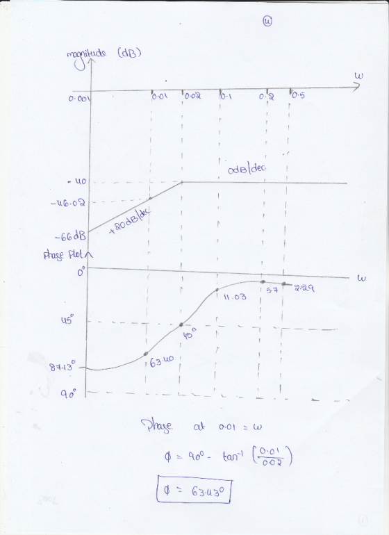
1. Derive the transfer function for the circuit shown below. Plot H(s) versus frequency in Hertz, on a semilog scale. Ri 11.3 k Ri 22.6 k R R = 68.1 kN R3 C C 0.01 uF R2 Vout(s) Vin(s) C2 10 (s+5) H(s) = (s+100)(s5000) , (a) draw the magnitude Bode plot 2. For the transfer function and find the approximate maximum value of (H(jw) in dB, (b) find the value of w where 1 for w>5...
QUESTION #2 PLEASE
1. Derive the transfer function for the circuit shown below. Plot H(s) versus frequency in Hertz, on a semilog scale. Ri 11.3 k Ri 22.6 k R R = 68.1 kN R3 C C 0.01 uF R2 Vout(s) Vin(s) C2 10 (s+5) H(s) = (s+100)(s5000) , (a) draw the magnitude Bode plot 2. For the transfer function and find the approximate maximum value of (H(jw) in dB, (b) find the value of w where 1 for w>5...
Given the circuit below: R3 C1 Vout C2 R1 R3 Vin R2 ts 1 a) derive the transfer function between ...
 Given the circuit below: R3 C1 Vout C2 R1 R3 Vin R2 ts 1 a) derive the transfer function between the input and the output in terms of R1,C1,R2,C2 b) For this and all other parts below, assume Izl<Ipl, i..e that D(s) is a lead-type compensator. The transfer function is written in the following format ts 1 Express quantities K, z, p using R1,C1,R2,C2 Also, express Κα, α, τ using K,z, p c) Observe the values of s-jw on the...
Please answer all parts thank you 6. [15 POINTS] Consider a passive low-pass filter as shown...
 Please answer all parts thank
you
6. [15 POINTS] Consider a passive low-pass filter as shown below. 1k2 + - m - + Vin(t) 1 mF Vout(t) a) Derive a transfer function for the above circuit. b) Derive a time-domain expression for the unit impulse response of the circuit. Also, plot the impulse response as a function of time. c) Derive a time-domain expression for the unit step response of the circuit. Also, plot the step response as a function...
Please answer all parts thank
you
6. [15 POINTS] Consider a passive low-pass filter as shown below. 1k2 + - m - + Vin(t) 1 mF Vout(t) a) Derive a transfer function for the above circuit. b) Derive a time-domain expression for the unit impulse response of the circuit. Also, plot the impulse response as a function of time. c) Derive a time-domain expression for the unit step response of the circuit. Also, plot the step response as a function...
Vout(s) Vin(s) For the circuit shown below, derive the conditions that will make the trasnfer fun...
 Please show all work.
Vout(s) Vin(s) For the circuit shown below, derive the conditions that will make the trasnfer function--= H(s) = , for the following OPAMP Models: S+1 out s+1 2 Av1x106 out (s+1)x (s+1x10⁶) C1 in V3 10μ R1 100k AC 1 PULSE(0 10 1n 1n 1 2) .ac oct 20 1 1000g
Vout(s) Vin(s) For the circuit shown below, derive the conditions that will make the trasnfer function--= H(s) = , for the following OPAMP Models: S+1...
Please show all work.
Vout(s) Vin(s) For the circuit shown below, derive the conditions that will make the trasnfer function--= H(s) = , for the following OPAMP Models: S+1 out s+1 2 Av1x106 out (s+1)x (s+1x10⁶) C1 in V3 10μ R1 100k AC 1 PULSE(0 10 1n 1n 1 2) .ac oct 20 1 1000g
Vout(s) Vin(s) For the circuit shown below, derive the conditions that will make the trasnfer function--= H(s) = , for the following OPAMP Models: S+1...
Problem 2 An RC circuit ( with an active component) has the following transfer function (where...
 Problem 2 An RC circuit ( with an active component) has the following transfer function (where R and Care positive) H(s) - Vout(8) _R|| R/10k12 Vin(8) 10KN 1 + $RC Where s = jw Find the value of the resistor and the value of the capacitor so that: for w = 0 rad/s, H(jw)lde = +12dB at f = 1kHz, |H(jw)lab = +9dB Problem 3 The transfer function of a circuit is given by H(S) = Vout(s) Vin(s) Where s...
P. 1. Answer the following questions about electric circuits. (1) Derive the transfer function for this...
 P. 1. Answer the following questions about electric circuits. (1) Derive the transfer function for this circuit R1 Vin out (2) Derive the transfer function for this circuit. R1 C1 C2 Voue in (3) Let R, 100[0], R2-1Mn2[mF). G 200[nF] in (2). Draw the Bode plot for the circuit.
Q11 (20pts.): For the circuit shown below Derive the transfer function, H(s) assuming the OPAMP's transfer...
 Q11 (20pts.): For the circuit shown below Derive the transfer function, H(s) assuming the OPAMP's transfer function is. If you like you can assumeA 106 Plot the bode plot of H(s) Derive the time domain step response. Plot the time domain step response This is a tricky problem! The LTspice file can be found here. .tran 2 V1 U1 out V2 R1 R2 in V3 1k 10k PULSE(-5 50 1102)
1. (20 points). A transfer function has the following zeros and poles: zero at s=-105 and s= poles at s-100 and s--1000. The magnitude of the transfer function at ω= 105 rad/s is equal 100. Find the...
 1. (20 points). A transfer function has the following zeros and poles: zero at s=-105 and s= poles at s-100 and s--1000. The magnitude of the transfer function at ω= 105 rad/s is equal 100. Find the transfer function T(s) and sketch Bode plots for the magnitude and phase, ˇ
1. (20 points). A transfer function has the following zeros and poles: zero at s=-105 and s= poles at s-100 and s--1000. The magnitude of the transfer function at ω=...
1. (20 points). A transfer function has the following zeros and poles: zero at s=-105 and s= poles at s-100 and s--1000. The magnitude of the transfer function at ω= 105 rad/s is equal 100. Find the transfer function T(s) and sketch Bode plots for the magnitude and phase, ˇ
1. (20 points). A transfer function has the following zeros and poles: zero at s=-105 and s= poles at s-100 and s--1000. The magnitude of the transfer function at ω=...
 Pre-Laboratory Task 4: Derive an expression for the magnitude of the transfer function, H(Go)Vout(jo)/Wn(j, and the phase of the transfer function LH (ja) for the LCR circuit in Figure 4. Plot H(ja)l and H(jo) vs. frequency (o) in the form of a Bode plot indicating the damping frequency and the value of |H(jo)| at the damping frequency. Also determine the 3dB frequency and the roll off rate for Ir(ja)1 when ω > ω3dB. Vounlius R 470Ω C 100 nF Figure...
 QUESTION #2 PLEASE
1. Derive the transfer function for the circuit shown below. Plot H(s) versus frequency in Hertz, on a semilog scale. Ri 11.3 k Ri 22.6 k R R = 68.1 kN R3 C C 0.01 uF R2 Vout(s) Vin(s) C2 10 (s+5) H(s) = (s+100)(s5000) , (a) draw the magnitude Bode plot 2. For the transfer function and find the approximate maximum value of (H(jw) in dB, (b) find the value of w where 1 for w>5...
QUESTION #2 PLEASE
1. Derive the transfer function for the circuit shown below. Plot H(s) versus frequency in Hertz, on a semilog scale. Ri 11.3 k Ri 22.6 k R R = 68.1 kN R3 C C 0.01 uF R2 Vout(s) Vin(s) C2 10 (s+5) H(s) = (s+100)(s5000) , (a) draw the magnitude Bode plot 2. For the transfer function and find the approximate maximum value of (H(jw) in dB, (b) find the value of w where 1 for w>5...
 Given the circuit below: R3 C1 Vout C2 R1 R3 Vin R2 ts 1 a) derive the transfer function between the input and the output in terms of R1,C1,R2,C2 b) For this and all other parts below, assume Izl<Ipl, i..e that D(s) is a lead-type compensator. The transfer function is written in the following format ts 1 Express quantities K, z, p using R1,C1,R2,C2 Also, express Κα, α, τ using K,z, p c) Observe the values of s-jw on the...
 Please answer all parts thank
you
6. [15 POINTS] Consider a passive low-pass filter as shown below. 1k2 + - m - + Vin(t) 1 mF Vout(t) a) Derive a transfer function for the above circuit. b) Derive a time-domain expression for the unit impulse response of the circuit. Also, plot the impulse response as a function of time. c) Derive a time-domain expression for the unit step response of the circuit. Also, plot the step response as a function...
Please answer all parts thank
you
6. [15 POINTS] Consider a passive low-pass filter as shown below. 1k2 + - m - + Vin(t) 1 mF Vout(t) a) Derive a transfer function for the above circuit. b) Derive a time-domain expression for the unit impulse response of the circuit. Also, plot the impulse response as a function of time. c) Derive a time-domain expression for the unit step response of the circuit. Also, plot the step response as a function...
 Please show all work.
Vout(s) Vin(s) For the circuit shown below, derive the conditions that will make the trasnfer function--= H(s) = , for the following OPAMP Models: S+1 out s+1 2 Av1x106 out (s+1)x (s+1x10⁶) C1 in V3 10μ R1 100k AC 1 PULSE(0 10 1n 1n 1 2) .ac oct 20 1 1000g
Vout(s) Vin(s) For the circuit shown below, derive the conditions that will make the trasnfer function--= H(s) = , for the following OPAMP Models: S+1...
Please show all work.
Vout(s) Vin(s) For the circuit shown below, derive the conditions that will make the trasnfer function--= H(s) = , for the following OPAMP Models: S+1 out s+1 2 Av1x106 out (s+1)x (s+1x10⁶) C1 in V3 10μ R1 100k AC 1 PULSE(0 10 1n 1n 1 2) .ac oct 20 1 1000g
Vout(s) Vin(s) For the circuit shown below, derive the conditions that will make the trasnfer function--= H(s) = , for the following OPAMP Models: S+1...
 Problem 2 An RC circuit ( with an active component) has the following transfer function (where R and Care positive) H(s) - Vout(8) _R|| R/10k12 Vin(8) 10KN 1 + $RC Where s = jw Find the value of the resistor and the value of the capacitor so that: for w = 0 rad/s, H(jw)lde = +12dB at f = 1kHz, |H(jw)lab = +9dB Problem 3 The transfer function of a circuit is given by H(S) = Vout(s) Vin(s) Where s...
 P. 1. Answer the following questions about electric circuits. (1) Derive the transfer function for this circuit R1 Vin out (2) Derive the transfer function for this circuit. R1 C1 C2 Voue in (3) Let R, 100[0], R2-1Mn2[mF). G 200[nF] in (2). Draw the Bode plot for the circuit.
 Q11 (20pts.): For the circuit shown below Derive the transfer function, H(s) assuming the OPAMP's transfer function is. If you like you can assumeA 106 Plot the bode plot of H(s) Derive the time domain step response. Plot the time domain step response This is a tricky problem! The LTspice file can be found here. .tran 2 V1 U1 out V2 R1 R2 in V3 1k 10k PULSE(-5 50 1102)
 1. (20 points). A transfer function has the following zeros and poles: zero at s=-105 and s= poles at s-100 and s--1000. The magnitude of the transfer function at ω= 105 rad/s is equal 100. Find the transfer function T(s) and sketch Bode plots for the magnitude and phase, ˇ
1. (20 points). A transfer function has the following zeros and poles: zero at s=-105 and s= poles at s-100 and s--1000. The magnitude of the transfer function at ω=...
1. (20 points). A transfer function has the following zeros and poles: zero at s=-105 and s= poles at s-100 and s--1000. The magnitude of the transfer function at ω= 105 rad/s is equal 100. Find the transfer function T(s) and sketch Bode plots for the magnitude and phase, ˇ
1. (20 points). A transfer function has the following zeros and poles: zero at s=-105 and s= poles at s-100 and s--1000. The magnitude of the transfer function at ω=...
Most questions answered within 3 hours.
-
In an Amide Synthesis reaction between acetic anhydride
& an unknown primary amine with aluminum oxide....
asked 1 minute ago -
Using #include <stdio.h>
6) Write a program that computes X^Y (X to the power of Y)....
asked 3 minutes ago -
Convert the following relation to third normal form:
CUSTOMER(CustomerID, CustomerName, CustomerCity,
PopulationOfCustomerCity)
asked 8 minutes ago -
How many permutations can be made using all the letters in the
word Connecticut?
asked 21 minutes ago -
Real World Example of Faradays Law. I understand the definition
but to further understand, I would...
asked 23 minutes ago -
Assume that an individual only consumes two goods: bread (B)
and tea (T). Bread is a...
asked 24 minutes ago -
c++
• Prompts the user to enter floating point numbers that
represent daily sale amounts at...
asked 21 minutes ago -
** Question 1: Consider the following discrete
probability distribution. The mean of this random variable is...
asked 24 minutes ago -
Search for the term "health disparities" (without question
marks) in the MeSH database of PubMed. What...
asked 27 minutes ago -
According to Lucas and Sargent, workers and firms have
rational expectations, and therefore if the Fed...
asked 51 minutes ago -
Write in full the Fault Tree Analysis of a gesture
control car.
asked 46 minutes ago -
Given the following requirements: we need to construct a
database that manages the hospital data. The...
asked 47 minutes ago