
Homework Answers


Add Answer to:
Problem 3 A 50-Hz transformer is operated from a 60 Hz supply. Assume that the load...
Problem (1): A 15-KVA, 2400:240-V, 60 Hz transformer has the following equivalent circuit parameters: R =...
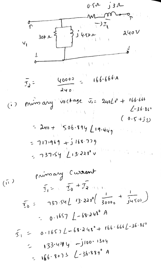
 Problem (1): A 15-KVA, 2400:240-V, 60 Hz transformer has the following equivalent circuit parameters: R = 2.522 R2 = 0.02522 Xi = 722 X = 0.0712 Re = 32 kl Xm = 11.5 k12 If the transformer is supplying a 10-kW, 0.8 PF lagging load at rated voltage, assuming the output voltage is the reference, draw the transformer's exact equivalent circuit referred to the primary (H.V) side and use it to calculate: 1. The input current 2. The input voltage...
1) A single-phase 50-kVA, 2400/240 volt, 60 Hz distribution transformer is used as a step-down tr...
 1) A single-phase 50-kVA, 2400/240 volt, 60 Hz distribution transformer is used as a step-down transformer at the load end of a 2400-volt feeder whose series impedance is (1.0+2.0) Ω. The equivalent series impedance of the transformer is (10+j25) Ω referred to the high voltage (primary) side. The transformer is delivering rated load at 0.8 power factor lagging and at rated secondary volitage. Neglect the transformer exciting curent. Using the transtormer raltings as base quantities work this problem in per...
A single-phase 100-kVA, 2400/240-volt, 60-Hz distribution transformer is used as a step-down transformer. The load, which...
 A single-phase 100-kVA, 2400/240-volt, 60-Hz distribution transformer is used as a step-down transformer. The load, which is connected to the 240-volt secondary winding, absorbs 80 kVA at 0.8 power factor lagging and is at 230 volts. Assuming an ideal transformer, calculate the following: a) primary voltage. b) load impedance. c) load impedance referred to the primary. d) the real and reactive power supplied to the primary winding
3.4 A single-phase 100-kVA, 2400/240-volt, 60-Hz distribution transformer is used as a step-down transformer. The load,...
3.4 A single-phase 100-kVA, 2400/240-volt, 60-Hz distribution transformer is used as a step-down transformer. The load, which is connected to the 240-volt secondary wind- ing, absorbs 80 kVA at 0.8 power factor lagging and is at 230 volts. Assuming an ideal transformer, calculate the following: (a) primary voltage, (b) load impedance, (c) load impedance referred to the primary, and (d) the real and reactive power sup- plied to the primary winding.
Choose the base power as 50-KVA, the primary base voltage as 2400-V, the secondary voltage as...
 Choose the base power as 50-KVA, the primary base voltage as 2400-V, the secondary voltage as 240-V: (a) Calculate and sketch the transformer equivalent circuit in per unit values' (b) The transformer is carrying rate load of 1.0 pu at.8 power factor lagging. Calculate the primary voltage in per unit. (c) Calculate the efficiency of the transformer at this load. A 50-KVA 2400/240-V, 60-Hz distribution transformer is tested with the following results: Open circuit Test Short Circuit Test Voc =...
4. The figure below shows the equivalent circuit of a 2400/240-V, 60-Hz transformer. The high-side leakage...
 4. The figure below shows the equivalent circuit of a 2400/240-V, 60-Hz transformer. The high-side leakage impedance is (1.2+j 2.0) 2. the low-side leakage impedance is (0.012 ti 0.02) S2, and Xm at the high-side is 1800 2. Neglect the Hysteresis and Eddy current loss resistance Rhe Calculate the input voltage if the output voltage is 240 V (rms). Given the load resistance is 1.5 12 and the power factor is 0.8 (lagging). ཉིས་པ་དེ། དེ་ | ༼ ། ༼། །
The short-circuit test readings for a 50-kVA 2400:240-V transformer are 48 V, 20.8 A, and 617...
 The short-circuit test readings for a 50-kVA 2400:240-V transformer are 48 V, 20.8 A, and 617 W, with the instruments located on the high-voltage side and the low-voltage side short- circuited. An open-circuit test with the low-voltage side energized gives instrument readings on that side of 240 V, 5.41 A, and 186 W. 1. Calculate the equivalent parameters of the transformer as referred to the high-voltage side. 2. Draw the equivalent approximate circuit of that transformer referred to the high...
A 200 kVA, 7200/600 V, 60 Hz transformer is operating at rated load and 0.9 p.f....
 A 200 kVA, 7200/600 V, 60 Hz transformer is operating at rated
load and 0.9 p.f. lagging. The core loss, winding resistances and
leakage reactances, expressed in per unit are 0.0056, 0.0133 and
0.0557 respectively. Determine: a) The efficiency. b) The voltage
regulation. c) The efficiency and regulation at 0.3 load and 0.8
p.f. lagging.
A 200 kVA, 7200/600 V, 60 Hz transformer is operating at rated load and 0.9 p.f. lagging. The core loss, winding resistances and leakage reactances,...
A 200 kVA, 7200/600 V, 60 Hz transformer is operating at rated
load and 0.9 p.f. lagging. The core loss, winding resistances and
leakage reactances, expressed in per unit are 0.0056, 0.0133 and
0.0557 respectively. Determine: a) The efficiency. b) The voltage
regulation. c) The efficiency and regulation at 0.3 load and 0.8
p.f. lagging.
A 200 kVA, 7200/600 V, 60 Hz transformer is operating at rated load and 0.9 p.f. lagging. The core loss, winding resistances and leakage reactances,...
A three phase 250 kVA 2400:415 V 50 Hz distribution transformer is constructed by connecting thre...
 A three phase 250 kVA 2400:415 V 50 Hz distribution transformer is constructed by connecting three single phase transformers in the Dynll vector group as shown in Fig.P1. The per phase equivalent circuit parameters on the high voltage side are: R1-0.72 Ω, Xi,-0.92 Ω, R2-0.70 Ω, Xp-0.90 Ω, R.-308.49 Ω, and X,,-44.61 Ω (a) Sketch the corresponding phasor diagram of the primary and secondary voltages for the Dynll vector group; lagging; terminal voltage is 415 V line to line, and...
6. A 20 kVA. 60 Hz, 8000/277 V transformer has the following impedances referred to the high volt...
 6. A 20 kVA. 60 Hz, 8000/277 V transformer has the following impedances referred to the high voltage side: Req-320, xe,-45Ω,R.-250kQ,Xm-30kQ. A) Calculate the voltage across rated load impedance with PF= 0.707 lagging when the transformer is connected to rated input voltage. B) Draw the phasor diagram showing the load voltage and current, voltage drop across the series impedance and voltage at the low voltage side of the ideal transformer, C) Calculate the efficiency of the transformer D) What adjustments...
 Problem (1): A 15-KVA, 2400:240-V, 60 Hz transformer has the following equivalent circuit parameters: R = 2.522 R2 = 0.02522 Xi = 722 X = 0.0712 Re = 32 kl Xm = 11.5 k12 If the transformer is supplying a 10-kW, 0.8 PF lagging load at rated voltage, assuming the output voltage is the reference, draw the transformer's exact equivalent circuit referred to the primary (H.V) side and use it to calculate: 1. The input current 2. The input voltage...
 1) A single-phase 50-kVA, 2400/240 volt, 60 Hz distribution transformer is used as a step-down transformer at the load end of a 2400-volt feeder whose series impedance is (1.0+2.0) Ω. The equivalent series impedance of the transformer is (10+j25) Ω referred to the high voltage (primary) side. The transformer is delivering rated load at 0.8 power factor lagging and at rated secondary volitage. Neglect the transformer exciting curent. Using the transtormer raltings as base quantities work this problem in per...
 A single-phase 100-kVA, 2400/240-volt, 60-Hz distribution transformer is used as a step-down transformer. The load, which is connected to the 240-volt secondary winding, absorbs 80 kVA at 0.8 power factor lagging and is at 230 volts. Assuming an ideal transformer, calculate the following: a) primary voltage. b) load impedance. c) load impedance referred to the primary. d) the real and reactive power supplied to the primary winding
 Choose the base power as 50-KVA, the primary base voltage as 2400-V, the secondary voltage as 240-V: (a) Calculate and sketch the transformer equivalent circuit in per unit values' (b) The transformer is carrying rate load of 1.0 pu at.8 power factor lagging. Calculate the primary voltage in per unit. (c) Calculate the efficiency of the transformer at this load. A 50-KVA 2400/240-V, 60-Hz distribution transformer is tested with the following results: Open circuit Test Short Circuit Test Voc =...
 4. The figure below shows the equivalent circuit of a 2400/240-V, 60-Hz transformer. The high-side leakage impedance is (1.2+j 2.0) 2. the low-side leakage impedance is (0.012 ti 0.02) S2, and Xm at the high-side is 1800 2. Neglect the Hysteresis and Eddy current loss resistance Rhe Calculate the input voltage if the output voltage is 240 V (rms). Given the load resistance is 1.5 12 and the power factor is 0.8 (lagging). ཉིས་པ་དེ། དེ་ | ༼ ། ༼། །
 The short-circuit test readings for a 50-kVA 2400:240-V transformer are 48 V, 20.8 A, and 617 W, with the instruments located on the high-voltage side and the low-voltage side short- circuited. An open-circuit test with the low-voltage side energized gives instrument readings on that side of 240 V, 5.41 A, and 186 W. 1. Calculate the equivalent parameters of the transformer as referred to the high-voltage side. 2. Draw the equivalent approximate circuit of that transformer referred to the high...
 A 200 kVA, 7200/600 V, 60 Hz transformer is operating at rated
load and 0.9 p.f. lagging. The core loss, winding resistances and
leakage reactances, expressed in per unit are 0.0056, 0.0133 and
0.0557 respectively. Determine: a) The efficiency. b) The voltage
regulation. c) The efficiency and regulation at 0.3 load and 0.8
p.f. lagging.
A 200 kVA, 7200/600 V, 60 Hz transformer is operating at rated load and 0.9 p.f. lagging. The core loss, winding resistances and leakage reactances,...
A 200 kVA, 7200/600 V, 60 Hz transformer is operating at rated
load and 0.9 p.f. lagging. The core loss, winding resistances and
leakage reactances, expressed in per unit are 0.0056, 0.0133 and
0.0557 respectively. Determine: a) The efficiency. b) The voltage
regulation. c) The efficiency and regulation at 0.3 load and 0.8
p.f. lagging.
A 200 kVA, 7200/600 V, 60 Hz transformer is operating at rated load and 0.9 p.f. lagging. The core loss, winding resistances and leakage reactances,...
 A three phase 250 kVA 2400:415 V 50 Hz distribution transformer is constructed by connecting three single phase transformers in the Dynll vector group as shown in Fig.P1. The per phase equivalent circuit parameters on the high voltage side are: R1-0.72 Ω, Xi,-0.92 Ω, R2-0.70 Ω, Xp-0.90 Ω, R.-308.49 Ω, and X,,-44.61 Ω (a) Sketch the corresponding phasor diagram of the primary and secondary voltages for the Dynll vector group; lagging; terminal voltage is 415 V line to line, and...
 6. A 20 kVA. 60 Hz, 8000/277 V transformer has the following impedances referred to the high voltage side: Req-320, xe,-45Ω,R.-250kQ,Xm-30kQ. A) Calculate the voltage across rated load impedance with PF= 0.707 lagging when the transformer is connected to rated input voltage. B) Draw the phasor diagram showing the load voltage and current, voltage drop across the series impedance and voltage at the low voltage side of the ideal transformer, C) Calculate the efficiency of the transformer D) What adjustments...
Most questions answered within 3 hours.
-
You have been married to your spouse for 10 years. You have two
small children (ages...
asked 1 hour ago -
Spiderman makes a leap from one building to
another. He starts on one building that is...
asked 1 hour ago -
A
symbol is something that stands for something else. What are the
symbols in education?what are...
asked 2 hours ago -
The charge to the left in the figure above has a
magnitude of 2.90 nC, and...
asked 3 hours ago -
Verify the MIRR is 9.29% given cash flows in years 1 and 2 of
$1,000 each,...
asked 4 hours ago -
Calculate the pH of a 5.7 M solution of aniline (C6H5NH2; Kb =
3.8 x 10^-10)
asked 6 hours ago -
LSL R3, R3, R12
Memory
Address
Orig.
Data
Updated
Data
Register
Orig.
Data
Updated
Data
0x84F0...
asked 6 hours ago -
Air at 100 kPa and density of 1.2 kg/m3 flows upward through a
5-cm diameter inclined...
asked 6 hours ago -
Define the following concepts in your own words: (a) stiffness,
(b) strength, (c) strain,
(d) ductility,...
asked 7 hours ago -
In C++
In this homework, you will be tasked with creating functions to
manipulate strings that...
asked 7 hours ago -
An isolated colony represents a pure culture. one rare occasions
, however , a colony can...
asked 7 hours ago -
*****DO NOT ANSWER THIS QUESTION IF YOU DON'T
KNOW*******Rights and Duties of Auditors; Minimum 4000
words...
asked 8 hours ago