
Homework Answers

Add Answer to:
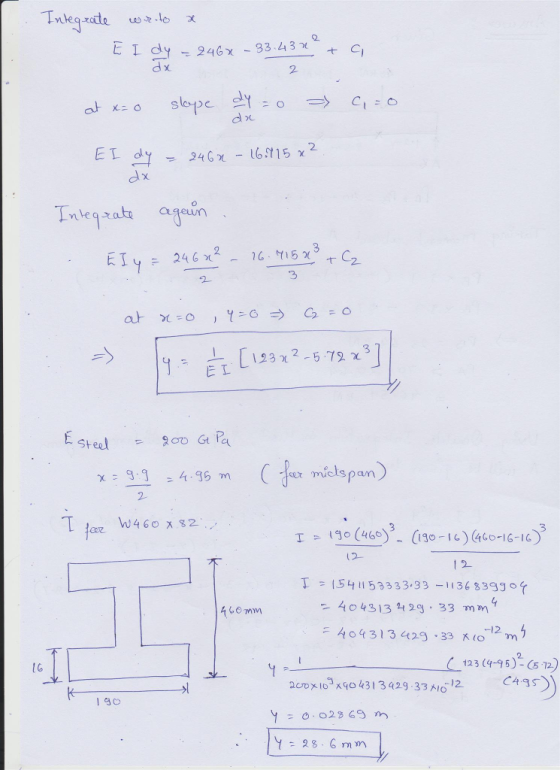
9-55.C Compute the deflection at the middle of a steel 460×82 (W 18×55) beam when it...
In Figure P9-55, the beam is a standard steel European IPB I-shape, 1 450x144.5. Compute the...
 In Figure P9-55, the beam is a standard steel European IPB I-shape, 1 450x144.5. Compute the deflection at the middle of the beam when it carries the load shown 40 kN 10kN 10 kN 10 kN 1.2 2.5 m 2.5 m 2.5 m 1.2
The simply supported beam consists of a W460 × 82 structural steel wide-flange shape [E =...
 The simply supported beam consists of a W460 × 82 structural
steel wide-flange shape [E = 200 GPa; I = 370 ×
106 mm4]. For the loading shown, determine
the beam deflection vC at point
C.
Assume P = 62 kN, w = 36 kN/m,
LAB = LBC = 3.9 m,
LCD = 1.9 m.
Chapter 10, Supplemental Question 053 Not Correct The samply supported beam cons sts o a W460 × 82 structural steel wide flange shape E :...
The simply supported beam consists of a W460 × 82 structural
steel wide-flange shape [E = 200 GPa; I = 370 ×
106 mm4]. For the loading shown, determine
the beam deflection vC at point
C.
Assume P = 62 kN, w = 36 kN/m,
LAB = LBC = 3.9 m,
LCD = 1.9 m.
Chapter 10, Supplemental Question 053 Not Correct The samply supported beam cons sts o a W460 × 82 structural steel wide flange shape E :...
For the steel beam shown in the figure, compute the slope at A and C. Also, determine the location and value of the maximum deflection. If the maximum deflection is not to exceed 0.6 i...
 For the steel beam shown in the figure, compute the slope at A and C. Also, determine the location and value of the maximum deflection. If the maximum deflection is not to exceed 0.6 in, what is the minimum required value of I? El is constant and E= 29000 ksi We were unable to transcribe this imageCompute the slope of the elastic curve at B and C and the deflection at C for the cantilever beam shown in the figure....
Question 3 For the simply supported steel beam with cross section and loading shown (see Figure...
 Question 3 For the simply supported steel beam with cross section and loading shown (see Figure 3a), knowing that uniformly distributed load w=60 kN/m, Young modulus E = 200 GPa, and yield stress Cyield=200 MPa (in both tension and compression). ул 15 mm w=60 kN/m ... 1 B A 15 mm + 300 mm IC - i 2.5m 1 1 15 mm 7.5m 1 150 mm Figure 3a (a) Check if: the beam is safe with respect to yielding (using...
Q2 The 10 m long simply supported beam is subjected to a uniformly distributed load w...
 Q2 The 10 m long simply supported beam is subjected to a uniformly distributed load w = 10 kN/m throughout and a point load P =10 kN at the midspan of the beam, as shown in Figure Q2 (a). The cross section of this beam is depicted in Figure Q2 (b), which consists of three equal rectangular steel members. Self-weight of the beam is neglected. 30 mm P= 10 KN W = 10 kN/m 200 mm 5 m 5 m...
Q2 The 10 m long simply supported beam is subjected to a uniformly distributed load w...
 Q2 The 10 m long simply supported beam is subjected to a uniformly distributed load w = 10 kN/m throughout and a point load P =10 kN at the midspan of the beam, as shown in Figure Q2 (a). The cross section of this beam is depicted in Figure Q2 (b), which consists of three equal rectangular steel members. Self-weight of the beam is neglected. 30 mm P = 10 kN W = 10 kN/m 200 mm 5 m 5...
Q2 The 10 m long simply supported beam is subjected to a uniformly distributed load w...
 Q2 The 10 m long simply supported beam is subjected to a uniformly distributed load w = 10 kN/m throughout and a point load P =10 kN at the midspan of the beam, as shown in Figure Q2 (a). The cross section of this beam is depicted in Figure Q2 (b), which consists of three equal rectangular steel members. Self-weight of the beam is neglected. 30 mm P = 10 kN w = 10 kN/m 200 mm 5 m 5...
For the cantilever steel beam shown below, find the deflection at point B. Q5 Assume that:...
 For the cantilever steel beam shown below, find the deflection at point B. Q5 Assume that: L 3 m, Mo 70 kN-m, E 200 GPa, I 129 x 106 mm4 and w= 15 kN/m. Mo Figure 5 [20 marks]
2. The governing differential equation that relates the deflection y of a beam to the load w ia w...
 2. The governing differential equation that relates the deflection y of a beam to the load w ia where both y and w are are functions of r. In the above equation, E is the modulus of elasticity and I is the moment of inertia of the beam. For the beam and loading shown in the figure, first de m, E = 200 GPa, 1 = 100 × 106 mm4 and uo 100 kN/m and determine the maximum deflection. Note...
The beam is shown in the figure below. Use the slope-deflection method. The support Ais pinned,...
 The beam is shown in the figure below. Use the slope-deflection method. The support Ais pinned, support B is a roller, and support C is fixed. Assume El = 21537 kNm2. The support at B settles by 73 mm (downwards). The segment AB is subjected to a uniformly distributed load w= 11 kN/m. The segment BC is subjected to a point load P = 91 KN. Enter the digit one in the answer box. The link will be provided on...
 In Figure P9-55, the beam is a standard steel European IPB I-shape, 1 450x144.5. Compute the deflection at the middle of the beam when it carries the load shown 40 kN 10kN 10 kN 10 kN 1.2 2.5 m 2.5 m 2.5 m 1.2
 The simply supported beam consists of a W460 × 82 structural
steel wide-flange shape [E = 200 GPa; I = 370 ×
106 mm4]. For the loading shown, determine
the beam deflection vC at point
C.
Assume P = 62 kN, w = 36 kN/m,
LAB = LBC = 3.9 m,
LCD = 1.9 m.
Chapter 10, Supplemental Question 053 Not Correct The samply supported beam cons sts o a W460 × 82 structural steel wide flange shape E :...
The simply supported beam consists of a W460 × 82 structural
steel wide-flange shape [E = 200 GPa; I = 370 ×
106 mm4]. For the loading shown, determine
the beam deflection vC at point
C.
Assume P = 62 kN, w = 36 kN/m,
LAB = LBC = 3.9 m,
LCD = 1.9 m.
Chapter 10, Supplemental Question 053 Not Correct The samply supported beam cons sts o a W460 × 82 structural steel wide flange shape E :...
 For the steel beam shown in the figure, compute the slope at A and C. Also, determine the location and value of the maximum deflection. If the maximum deflection is not to exceed 0.6 in, what is the minimum required value of I? El is constant and E= 29000 ksi We were unable to transcribe this imageCompute the slope of the elastic curve at B and C and the deflection at C for the cantilever beam shown in the figure....
 Question 3 For the simply supported steel beam with cross section and loading shown (see Figure 3a), knowing that uniformly distributed load w=60 kN/m, Young modulus E = 200 GPa, and yield stress Cyield=200 MPa (in both tension and compression). ул 15 mm w=60 kN/m ... 1 B A 15 mm + 300 mm IC - i 2.5m 1 1 15 mm 7.5m 1 150 mm Figure 3a (a) Check if: the beam is safe with respect to yielding (using...
 Q2 The 10 m long simply supported beam is subjected to a uniformly distributed load w = 10 kN/m throughout and a point load P =10 kN at the midspan of the beam, as shown in Figure Q2 (a). The cross section of this beam is depicted in Figure Q2 (b), which consists of three equal rectangular steel members. Self-weight of the beam is neglected. 30 mm P= 10 KN W = 10 kN/m 200 mm 5 m 5 m...
 Q2 The 10 m long simply supported beam is subjected to a uniformly distributed load w = 10 kN/m throughout and a point load P =10 kN at the midspan of the beam, as shown in Figure Q2 (a). The cross section of this beam is depicted in Figure Q2 (b), which consists of three equal rectangular steel members. Self-weight of the beam is neglected. 30 mm P = 10 kN W = 10 kN/m 200 mm 5 m 5...
 Q2 The 10 m long simply supported beam is subjected to a uniformly distributed load w = 10 kN/m throughout and a point load P =10 kN at the midspan of the beam, as shown in Figure Q2 (a). The cross section of this beam is depicted in Figure Q2 (b), which consists of three equal rectangular steel members. Self-weight of the beam is neglected. 30 mm P = 10 kN w = 10 kN/m 200 mm 5 m 5...
 For the cantilever steel beam shown below, find the deflection at point B. Q5 Assume that: L 3 m, Mo 70 kN-m, E 200 GPa, I 129 x 106 mm4 and w= 15 kN/m. Mo Figure 5 [20 marks]
 2. The governing differential equation that relates the deflection y of a beam to the load w ia where both y and w are are functions of r. In the above equation, E is the modulus of elasticity and I is the moment of inertia of the beam. For the beam and loading shown in the figure, first de m, E = 200 GPa, 1 = 100 × 106 mm4 and uo 100 kN/m and determine the maximum deflection. Note...
 The beam is shown in the figure below. Use the slope-deflection method. The support Ais pinned, support B is a roller, and support C is fixed. Assume El = 21537 kNm2. The support at B settles by 73 mm (downwards). The segment AB is subjected to a uniformly distributed load w= 11 kN/m. The segment BC is subjected to a point load P = 91 KN. Enter the digit one in the answer box. The link will be provided on...
Most questions answered within 3 hours.
-
1. why is toluene a stronger nucleophile than benzene?
2.why is phenol a stronger nucleophile than...
asked 3 minutes ago -
4. How can you solve for the density of the liquid from the
slope? Please show...
asked 3 minutes ago -
when 2053 j of heat is added to 46.3 g of hexane C6H14 the
temperature increases...
asked 26 minutes ago -
I need new and unique answers, please. (Use your own words,
don't copy and paste), Please...
asked 29 minutes ago -
MCL 445.111 et seq. deals with Home Solicitation Sales.
MCL stands for Michigan Compiled Laws which...
asked 20 minutes ago -
Which of the following items may not create an NOL?
a.
sole proprietorship loss
b.
personal...
asked 25 minutes ago -
A hypothetical solution forms between a solid and a liquid. The
values of the thermodynamic quantities...
asked 23 minutes ago -
a)An ideal heat pump is being considered for use in heating an
environment with a temperature...
asked 27 minutes ago -
.
Convert the following pairs of voltage and current waveforms to
phasor form. Each pair of...
asked 28 minutes ago -
A 6.5 cm diameter ball has a terminal speed of 22 m/s. What is
the ball's...
asked 42 minutes ago -
Name two areas of the human body with the highest concentration
of lymph nodes and speculate...
asked 46 minutes ago -
Angel Corporation has $10,000,000 of
8.0% 25 year bonds dated May 1, 2018 with interest payable...
asked 1 hour ago