9. An ideal Opamp has infinite input impedance but non-zero output impedance. The Opamp is used...
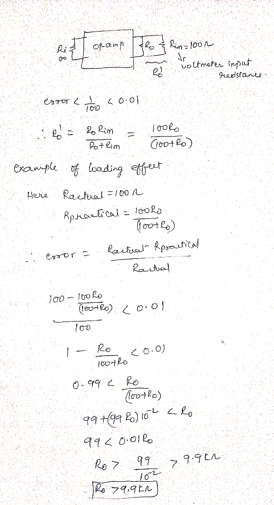
9. An ideal Opamp has infinite input impedance but non-zero output impedance. The Opamp is used as a voltage follower interface for connecting a biomeasurement device to a voltmeter. If the voltmeter has an input impedance of 100Ω, what must the Opamp output impedance be to give a measurement error of less than 1%?
Homework Answers
Add Answer to:
9. An ideal Opamp has infinite input impedance but non-zero
output impedance. The Opamp is used...
Although an ideal voltmeter has an infinite internal resistance, this theoretical ideal is usually not met...
 Although an ideal voltmeter has an infinite
internal resistance, this theoretical ideal is usually not met in
practice. The voltmeter in the Figure has an internal resistance of
7 x 10⁹ Ω and is used to measure the voltage across the
resistor R2 as shown. Attaching this non-ideal voltmeter
decreases the voltage across R2. Calculate the magnitude
of this decrease using an emf of 16 V and R1 =
R2 = 200 kΩ.
Although an ideal voltmeter has an infinite
internal resistance, this theoretical ideal is usually not met in
practice. The voltmeter in the Figure has an internal resistance of
7 x 10⁹ Ω and is used to measure the voltage across the
resistor R2 as shown. Attaching this non-ideal voltmeter
decreases the voltage across R2. Calculate the magnitude
of this decrease using an emf of 16 V and R1 =
R2 = 200 kΩ.
Although an ideal voltmeter has an infinite internal resistance, this theoretical ideal is usually not met...
 Although an ideal voltmeter has an infinite internal resistance, this theoretical ideal is usually not met in practice. The voltmeter in the Figure has an internal resistance of 4 x 10⁹ 2 and is used to measure the voltage across the resistor R2 as shown. Attaching this non-ideal voltmeter decreases the voltage across R2. Calculate the magnitude of this decrease using an emf of 14 V and R1 = R2 = 250 ks2. Submit Answer This question expects a numeric...
An ideal op-amp has infinite output impedance. Select one: O True O False A buffer circuit...
 An ideal op-amp has infinite output impedance. Select one: O True O False A buffer circuit is characterized by infinite gain. Select one: O True O False
The gain of the non-inverting amplifier is set by the values of the resistors connected to the op...
 The gain of the non-inverting amplifier is set by the values of the resistors connected to the op- .amp can never be less than 1, even when RB is very high and RT equals 0 A voltage divider is a circuit involving two resistors in series All above is .1 correct Which statement not correct for Ideal operational amplifier Infinite open loop gain AOL for differential .1 .signa Zero gain for the common mode signal .Zero output impedance .noninfinite bandwidth...
9. A circuit that combines a zener regulator and an emitter follower is referred to as...
 9. A circuit that combines a zener regulator and an emitter follower is referred to as A. An emitter regulator B. A follower regulator C. A zener follower D. A zener diode 10. Small load resistances that would overload a CE amplifier can be used with an emitter follower because an emitter follower A. steps up impedance B. amplifies high frequencies better C. has a higher voltage gain D. cannot amplify current 11. The emitter-follower amplifier has a A. low...
Exercise1 R1 R3 Vi vo R4 u2 In the figure above the opamp is ideal. Please...
 Exercise1 R1 R3 Vi vo R4 u2 In the figure above the opamp is ideal. Please answer the following questions: Question 1 1 pts Exercise 1 Part 1/3: Assuming R1-500Ω and R3-3kQ, what is the value of R4 so that vo-3V when v1-0V and V2-5V None of the options are correct 500Ω 2500 12k0 Question 2 1 pts Exercise 1 Part 2/3: Assuming R3=800Ω and R4:500Ω what is the value of R1 so that a de input current offset equal...
An ideal analog-to-digital converter has 6 bits and a 1V input full-scale input voltage. What is...
An ideal analog-to-digital converter has 6 bits and a 1V input full-scale input voltage. What is the ideal minimum quantization error in volts? Also,what is the dynamic range of a 9-bit AtoD in dB?
Loading Error Example Problem: A 0-5000psi pressure transducer generates .02Volts/Volt F.S.O and has a output impedance...
 Loading Error Example Problem: A 0-5000psi pressure transducer generates .02Volts/Volt F.S.O and has a output impedance of 120 Ohms it will be used as an input signal to a signal conditioning amplifier with 25KOhms input impedance. The transducer will be powered with a 5vdc power supply A. What is the expected Loading Error? B. What is the FSO with no Loading Error? C. What is the volt/psi value for the xdcr? D. The DC power supply is poorly regulated and...
A boost converter has an input of 5 V and an output of 25 W at...
A boost converter has an input of 5 V and an output of 25 W at 15 V. The minimum inductor current must be no less than 50 percent of the average. The output voltage ripple must be less than 1 percent. The switching frequency is 300 kHz. Determine the duty ratio, minimum inductor value, and minimum capacitor value.
Design a buck converter which has an output of 12V from an input of 18V. The...
 Design a buck converter which has an output of 12V from an input of 18V. The output power is 10W. The output voltage ripple must be no more than 100mV peak to peak. Specify the duty ratio, switching frequency is 500kHz, ton, and inductor and capacitor values. Design for continuous inductor current. Assume ideal conditions, and assume the output current is symmetric
 Although an ideal voltmeter has an infinite internal resistance, this theoretical ideal is usually not met in practice. The voltmeter in the Figure has an internal resistance of 4 x 10⁹ 2 and is used to measure the voltage across the resistor R2 as shown. Attaching this non-ideal voltmeter decreases the voltage across R2. Calculate the magnitude of this decrease using an emf of 14 V and R1 = R2 = 250 ks2. Submit Answer This question expects a numeric...
 An ideal op-amp has infinite output impedance. Select one: O True O False A buffer circuit is characterized by infinite gain. Select one: O True O False
 The gain of the non-inverting amplifier is set by the values of the resistors connected to the op- .amp can never be less than 1, even when RB is very high and RT equals 0 A voltage divider is a circuit involving two resistors in series All above is .1 correct Which statement not correct for Ideal operational amplifier Infinite open loop gain AOL for differential .1 .signa Zero gain for the common mode signal .Zero output impedance .noninfinite bandwidth...
 9. A circuit that combines a zener regulator and an emitter follower is referred to as A. An emitter regulator B. A follower regulator C. A zener follower D. A zener diode 10. Small load resistances that would overload a CE amplifier can be used with an emitter follower because an emitter follower A. steps up impedance B. amplifies high frequencies better C. has a higher voltage gain D. cannot amplify current 11. The emitter-follower amplifier has a A. low...
 Exercise1 R1 R3 Vi vo R4 u2 In the figure above the opamp is ideal. Please answer the following questions: Question 1 1 pts Exercise 1 Part 1/3: Assuming R1-500Ω and R3-3kQ, what is the value of R4 so that vo-3V when v1-0V and V2-5V None of the options are correct 500Ω 2500 12k0 Question 2 1 pts Exercise 1 Part 2/3: Assuming R3=800Ω and R4:500Ω what is the value of R1 so that a de input current offset equal...
 Loading Error Example Problem: A 0-5000psi pressure transducer generates .02Volts/Volt F.S.O and has a output impedance of 120 Ohms it will be used as an input signal to a signal conditioning amplifier with 25KOhms input impedance. The transducer will be powered with a 5vdc power supply A. What is the expected Loading Error? B. What is the FSO with no Loading Error? C. What is the volt/psi value for the xdcr? D. The DC power supply is poorly regulated and...
 Design a buck converter which has an output of 12V from an input of 18V. The output power is 10W. The output voltage ripple must be no more than 100mV peak to peak. Specify the duty ratio, switching frequency is 500kHz, ton, and inductor and capacitor values. Design for continuous inductor current. Assume ideal conditions, and assume the output current is symmetric
Most questions answered within 3 hours.
-
Steven can afford car payments of $300 a month for 72 months.
The bank will lend...
asked 5 minutes ago -
Embedded
System..
1.
Analyze
the instruction
sets below.
LDR R1, [R0,
#0x08]
SUB R1, R1,
R2,...
asked 10 minutes ago -
Use proper sentence structure to communicate clearly.
Choose the correct sentence structure in each of the...
asked 9 minutes ago -
There are investors who claim they only invest in companies with
great products and outstanding management,...
asked 12 minutes ago -
what is employee/ employer relations ?
why is Employee/ Employer relation is important in the context...
asked 30 minutes ago -
Explain the relationship between tests of acquisition and
payment cycle and tests of accounts payable. Give...
asked 29 minutes ago -
A hot-air balloon is descending with a velocity of (−2.00m/s)y^.
A champagne bottle is opened to...
asked 47 minutes ago -
1. When a nearsighted person looks at an object that is in the
distance with their...
asked 2 hours ago -
QUESTION 8
Both of these statements will store the same value in the
variable $number
$number...
asked 2 hours ago -
The price of 1 lb of potatoes is $1.75. If all the potatoes sold
today at...
asked 3 hours ago -
Garcia Company issues 20.00%, 15-year bonds with a par value of
$470,000 and semiannual interest payments....
asked 3 hours ago -
In C++ Programming, Try using loops only.
This lab demonstrates the use of the While Loop...
asked 4 hours ago