

Homework Answers

Add Answer to:
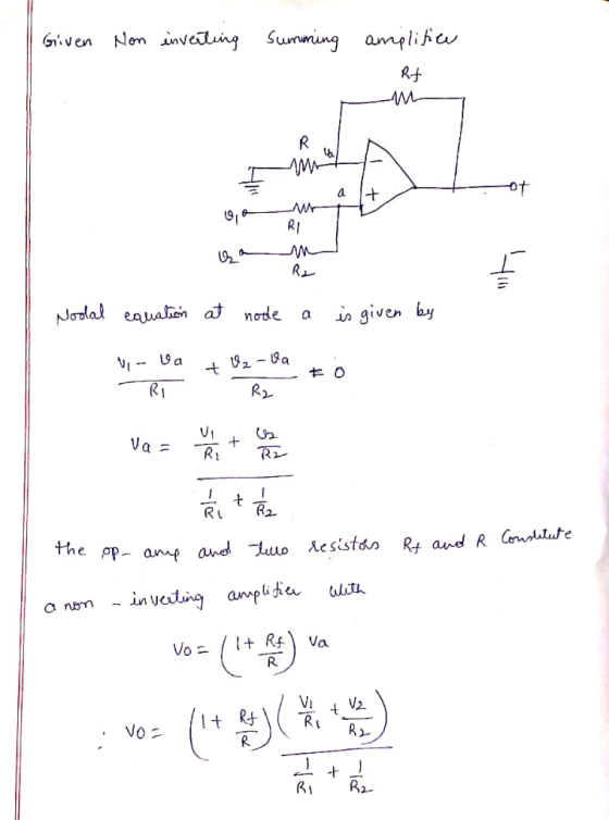
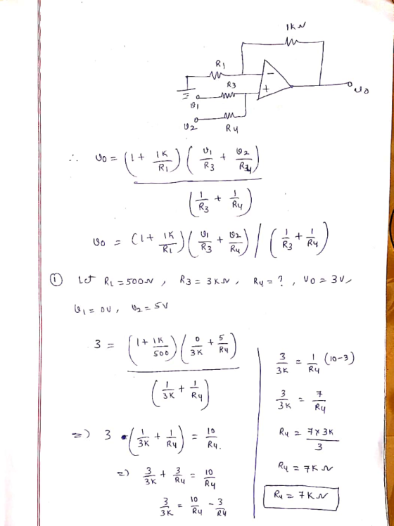
Exercise1 R1 R3 Vi vo R4 u2 In the figure above the opamp is ideal. Please...
Assuming an ideal op-amp in the following circuit, find output voltage, Vo if R1= 2 K2,...
 Assuming an ideal op-amp in the following circuit, find output voltage, Vo if R1= 2 K2, R2=8 K12, R3=3.8 KS2, R4=6 KI2, R5=15 KS2, R6=3.8 KN, RL=9.8 K12, V1=1V, 12=0.5 mA and V3=2.2 V. } R6 R1 w R5 w + Vo + } RL 12 R2 V1 R3 R4 + +1 V3 Using the above circuit, but consider the following component values: R1= 2 KN R2=8 K2, R3=4.1 K12, R4=6 KI2, R5=17.0 K12, R6=15 KI, RL=10 KI, V1=1V, 12=0.5mA...
Assuming an ideal op-amp in the following circuit, find output voltage, Vo if R1= 2 KS,...
 Assuming an ideal op-amp in the following circuit, find output voltage, Vo if R1= 2 KS, R2=8 KN, R3=3.4 KA, R4=6 KN, R5=20 KN, R6=2.9 KN, RL=12.5 KN, V1=1V, 12=0.5 mA and V3=3.1 V. R6 R1 R5 VO + RL 12 R2 V1 R3 { R4 w V3 Answer: "V
Assuming an ideal op-amp in the following circuit, find output voltage, Vo if R1= 2 K2,...
 Assuming an ideal op-amp in the following circuit, find output voltage, Vo if R1= 2 K2, R2=8 K2, R3=5.1 K2, R4=6 KN, R5=14 KN, R6=4.2 KS, RL=10.3 KS, V1=1V, 12=0.5 mA and V3=3.2 V. R6 R1 R5 Vo w + * RL + 12 R2 V1 R3 R4 V3 Answer: OV Using the above circuit, but consider the following component values: R1= 2 K12 R2=8 K2, R3=2.9 K2, R4=6 KI2, R5=10.8 K92, R6=15 KO, RL=10 K2, V1=1V, 12=0.5mA and V3=2V....
Assuming an ideal op-amp in the following circuit, find output voltage, Vo if R1= 2 K12,...
 Assuming an ideal op-amp in the following circuit, find output voltage, Vo if R1= 2 K12, R2=8 KN, R3=3.9 KN, R4=6 KN, R5=18 K2, R6=4.4 KN, RL=12.5 KN, V1=1V, 12=0.5 mA and V3=3.4 V. R6 R1 R5 Vo + + RL R2 V1 R3 R4 + V3 Answer: LOV Using the above circuit, but consider the following component values: R1= 2 KO2 R2=8 K12, R3=3.6 K12, R4=6 K12, R5=16.9 KN, R6=15 KN, RL=10 KO, V1=1V, 12=0.5mA and V3=2V. What is...
1609) Refer to Figure 1609 with an ideal opamp. R1=2.9k ohms, R2=1.8k ohms, Power supply input...
 1609) Refer to Figure 1609 with an ideal opamp. R1=2.9k ohms, R2=1.8k ohms, Power supply input voltages are V1=1.7 volts, V2=1.7 volts. Also note R3=1.7k ohms. Determine Vo. Only one answer is required. ans:5 Figure 1609
For the circuit shown below: Preview In terms of Vo, R1, R2, R3, R4 C1, t, and s what is the time domain equation for the voltage at node out? Preview and s what is the s-domain equation the voltage...
 For the circuit shown below: Preview In terms of Vo, R1, R2, R3, R4 C1, t, and s what is the time domain equation for the voltage at node out? Preview and s what is the s-domain equation the voltage at node out? In terms of Vo, RI, R2, R3,R4, C1, t, Preview and s what is the equation for τ? In terms ofVo, RI, R2, R3, R4, Cl, t, Ifthe voltage V1 at time-0 is 3 V RI=4 kQ,...
PROTEUS +15V R5 1M R3 750 C3 HE Dvout luf Q1 ZVN2110 R1 C1 R4 100F...
 PROTEUS
+15V R5 1M R3 750 C3 HE Dvout luf Q1 ZVN2110 R1 C1 R4 100F V1 VSINE R6 1M R2 1k C2 Tur Figure 8.2. CS Amplifier with a bypassed Rs 1. Design and build the common source amplifier as shown in Figure 8.2. 2. Provide Vai= 100 m Vpp at 5 KHz frequency and measure the output voltage. 3. Record pictures of the input and output waveforms and calculate the gain. 4. Vary Vsig (Try 1V, 400mV, 100mV)...
PROTEUS
+15V R5 1M R3 750 C3 HE Dvout luf Q1 ZVN2110 R1 C1 R4 100F V1 VSINE R6 1M R2 1k C2 Tur Figure 8.2. CS Amplifier with a bypassed Rs 1. Design and build the common source amplifier as shown in Figure 8.2. 2. Provide Vai= 100 m Vpp at 5 KHz frequency and measure the output voltage. 3. Record pictures of the input and output waveforms and calculate the gain. 4. Vary Vsig (Try 1V, 400mV, 100mV)...
SIMULATION EXERCISE # 3 Mesh Analysis" Given the following network: R1 V2 2k 5V V1 k R4 Vs volls 12 Tk 3k R3 R5 1. Simulate the above network using Pspice, Choose a value of Vs for the left...
 SIMULATION EXERCISE # 3 Mesh Analysis" Given the following network: R1 V2 2k 5V V1 k R4 Vs volls 12 Tk 3k R3 R5 1. Simulate the above network using Pspice, Choose a value of Vs for the left hand voltage source. Have values for the mesh currents I, and I2 appear on your schematic. By hand calculations use mesh analysis to determine the values of I1 and I2. Show your work
SIMULATION EXERCISE # 3 Mesh Analysis" Given the...
SIMULATION EXERCISE # 3 Mesh Analysis" Given the following network: R1 V2 2k 5V V1 k R4 Vs volls 12 Tk 3k R3 R5 1. Simulate the above network using Pspice, Choose a value of Vs for the left hand voltage source. Have values for the mesh currents I, and I2 appear on your schematic. By hand calculations use mesh analysis to determine the values of I1 and I2. Show your work
SIMULATION EXERCISE # 3 Mesh Analysis" Given the...
please help ASAP with the quiz R1 3 R2 R3 Find Is (round to one decimal...
 please help ASAP with the quiz
R1 3 R2 R3 Find Is (round to one decimal place) Vs= 2. R1= 36 R2=5 R3=14 M Gmail QueSLIUITO WO- "11" is a current Branch Mesh 1 pts Question 9 (Hint: Voltages in series can be added together if the voltages are aiding each other. The net voltage will be their sum. If the voltages are opposing then the net voltage is their difference) V1= 2 ohms V2= 7ohms R1= 18ohms R2= 20ohms...
please help ASAP with the quiz
R1 3 R2 R3 Find Is (round to one decimal place) Vs= 2. R1= 36 R2=5 R3=14 M Gmail QueSLIUITO WO- "11" is a current Branch Mesh 1 pts Question 9 (Hint: Voltages in series can be added together if the voltages are aiding each other. The net voltage will be their sum. If the voltages are opposing then the net voltage is their difference) V1= 2 ohms V2= 7ohms R1= 18ohms R2= 20ohms...
3 Circuit C2 R1 Connect to Vo Unity Gair 470 0.1uF Follower Ground Output C1 4700 R2 R3 1000 C3 luF Figure 1. AC Test C...
 3 Circuit C2 R1 Connect to Vo Unity Gair 470 0.1uF Follower Ground Output C1 4700 R2 R3 1000 C3 luF Figure 1. AC Test Circuit. 5 LTspice Simulation » Use LTspice to simulate the circuit shown in Figure 1. . The AC voltage source should have an amplitude of 5V and a frequency of 60Hz. When you enter the parameters in LTspice, you should see them displayed on the schematic as follows SINE(0 5 60000 1000) * Graph the...
 Assuming an ideal op-amp in the following circuit, find output voltage, Vo if R1= 2 K2, R2=8 K12, R3=3.8 KS2, R4=6 KI2, R5=15 KS2, R6=3.8 KN, RL=9.8 K12, V1=1V, 12=0.5 mA and V3=2.2 V. } R6 R1 w R5 w + Vo + } RL 12 R2 V1 R3 R4 + +1 V3 Using the above circuit, but consider the following component values: R1= 2 KN R2=8 K2, R3=4.1 K12, R4=6 KI2, R5=17.0 K12, R6=15 KI, RL=10 KI, V1=1V, 12=0.5mA...
 Assuming an ideal op-amp in the following circuit, find output voltage, Vo if R1= 2 KS, R2=8 KN, R3=3.4 KA, R4=6 KN, R5=20 KN, R6=2.9 KN, RL=12.5 KN, V1=1V, 12=0.5 mA and V3=3.1 V. R6 R1 R5 VO + RL 12 R2 V1 R3 { R4 w V3 Answer: "V
 Assuming an ideal op-amp in the following circuit, find output voltage, Vo if R1= 2 K2, R2=8 K2, R3=5.1 K2, R4=6 KN, R5=14 KN, R6=4.2 KS, RL=10.3 KS, V1=1V, 12=0.5 mA and V3=3.2 V. R6 R1 R5 Vo w + * RL + 12 R2 V1 R3 R4 V3 Answer: OV Using the above circuit, but consider the following component values: R1= 2 K12 R2=8 K2, R3=2.9 K2, R4=6 KI2, R5=10.8 K92, R6=15 KO, RL=10 K2, V1=1V, 12=0.5mA and V3=2V....
 Assuming an ideal op-amp in the following circuit, find output voltage, Vo if R1= 2 K12, R2=8 KN, R3=3.9 KN, R4=6 KN, R5=18 K2, R6=4.4 KN, RL=12.5 KN, V1=1V, 12=0.5 mA and V3=3.4 V. R6 R1 R5 Vo + + RL R2 V1 R3 R4 + V3 Answer: LOV Using the above circuit, but consider the following component values: R1= 2 KO2 R2=8 K12, R3=3.6 K12, R4=6 K12, R5=16.9 KN, R6=15 KN, RL=10 KO, V1=1V, 12=0.5mA and V3=2V. What is...
 1609) Refer to Figure 1609 with an ideal opamp. R1=2.9k ohms, R2=1.8k ohms, Power supply input voltages are V1=1.7 volts, V2=1.7 volts. Also note R3=1.7k ohms. Determine Vo. Only one answer is required. ans:5 Figure 1609
 For the circuit shown below: Preview In terms of Vo, R1, R2, R3, R4 C1, t, and s what is the time domain equation for the voltage at node out? Preview and s what is the s-domain equation the voltage at node out? In terms of Vo, RI, R2, R3,R4, C1, t, Preview and s what is the equation for τ? In terms ofVo, RI, R2, R3, R4, Cl, t, Ifthe voltage V1 at time-0 is 3 V RI=4 kQ,...
 PROTEUS
+15V R5 1M R3 750 C3 HE Dvout luf Q1 ZVN2110 R1 C1 R4 100F V1 VSINE R6 1M R2 1k C2 Tur Figure 8.2. CS Amplifier with a bypassed Rs 1. Design and build the common source amplifier as shown in Figure 8.2. 2. Provide Vai= 100 m Vpp at 5 KHz frequency and measure the output voltage. 3. Record pictures of the input and output waveforms and calculate the gain. 4. Vary Vsig (Try 1V, 400mV, 100mV)...
PROTEUS
+15V R5 1M R3 750 C3 HE Dvout luf Q1 ZVN2110 R1 C1 R4 100F V1 VSINE R6 1M R2 1k C2 Tur Figure 8.2. CS Amplifier with a bypassed Rs 1. Design and build the common source amplifier as shown in Figure 8.2. 2. Provide Vai= 100 m Vpp at 5 KHz frequency and measure the output voltage. 3. Record pictures of the input and output waveforms and calculate the gain. 4. Vary Vsig (Try 1V, 400mV, 100mV)...
 SIMULATION EXERCISE # 3 Mesh Analysis" Given the following network: R1 V2 2k 5V V1 k R4 Vs volls 12 Tk 3k R3 R5 1. Simulate the above network using Pspice, Choose a value of Vs for the left hand voltage source. Have values for the mesh currents I, and I2 appear on your schematic. By hand calculations use mesh analysis to determine the values of I1 and I2. Show your work
SIMULATION EXERCISE # 3 Mesh Analysis" Given the...
SIMULATION EXERCISE # 3 Mesh Analysis" Given the following network: R1 V2 2k 5V V1 k R4 Vs volls 12 Tk 3k R3 R5 1. Simulate the above network using Pspice, Choose a value of Vs for the left hand voltage source. Have values for the mesh currents I, and I2 appear on your schematic. By hand calculations use mesh analysis to determine the values of I1 and I2. Show your work
SIMULATION EXERCISE # 3 Mesh Analysis" Given the...
 please help ASAP with the quiz
R1 3 R2 R3 Find Is (round to one decimal place) Vs= 2. R1= 36 R2=5 R3=14 M Gmail QueSLIUITO WO- "11" is a current Branch Mesh 1 pts Question 9 (Hint: Voltages in series can be added together if the voltages are aiding each other. The net voltage will be their sum. If the voltages are opposing then the net voltage is their difference) V1= 2 ohms V2= 7ohms R1= 18ohms R2= 20ohms...
please help ASAP with the quiz
R1 3 R2 R3 Find Is (round to one decimal place) Vs= 2. R1= 36 R2=5 R3=14 M Gmail QueSLIUITO WO- "11" is a current Branch Mesh 1 pts Question 9 (Hint: Voltages in series can be added together if the voltages are aiding each other. The net voltage will be their sum. If the voltages are opposing then the net voltage is their difference) V1= 2 ohms V2= 7ohms R1= 18ohms R2= 20ohms...
 3 Circuit C2 R1 Connect to Vo Unity Gair 470 0.1uF Follower Ground Output C1 4700 R2 R3 1000 C3 luF Figure 1. AC Test Circuit. 5 LTspice Simulation » Use LTspice to simulate the circuit shown in Figure 1. . The AC voltage source should have an amplitude of 5V and a frequency of 60Hz. When you enter the parameters in LTspice, you should see them displayed on the schematic as follows SINE(0 5 60000 1000) * Graph the...
Most questions answered within 3 hours.
-
What percent of revenue does net income represent for each
year?
Total Revenue
2017 = 60,319,000...
asked 7 minutes ago -
For Ti+2 (Z=22). Determine the correct ground state
& # of microstates. Use the correct tanabe...
asked 10 minutes ago -
Why did so many investment banks have to start buying CDO’s and
other mortgaged backed securities...
asked 25 minutes ago -
The mean cost of domestic airfares in the United States rose to
an all-time high of...
asked 36 minutes ago -
1.Magazine Luiza is a Brazilian retail chain for consumer
electronics. The company currently has 100 stores...
asked 35 minutes ago -
What is the molarity of ZnCl2 that forms when 25.0 g of zinc
completely reacts with...
asked 37 minutes ago -
For independent X and Y, we have probability density function
for them where pdf of X...
asked 47 minutes ago -
The decomposition of SO2Cl2 is first order in SO2Cl2 and has a
rate constant of 1.42...
asked 43 minutes ago -
How do I convert from volume percent to mole percent in the
distillation lab? ethy acetate...
asked 50 minutes ago -
8. An air-plane has an effective wing surface area of 14.0 m²
that is generating the...
asked 51 minutes ago -
A railroad worker was a person who worked on setting and moving
railroad tracks. In securing...
asked 49 minutes ago -
using RECURSIVE Functions in Java, create a public static String
doubleLetters (String word)
For ex) that...
asked 56 minutes ago