
Homework Answers
Given data:
The maximum allowable bending stress,  = 24 ksi
The maximum allowable shear stress,  = 24 ksi
P = 3 kip
Solution:
Draw the free body diagram of the beam.

Write the equilibrium equation of forces along the x-axis.

Take the moment of all the forces at point A.
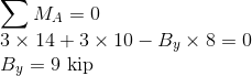
Write the equilibrium equation of forces along the x-axis.

The shear force details at x = 0 to 14 ft
Shear force at x = 0 is -3 kip.
Shear force at x =8 ft is -3+9 = 6 kip.
Shear force at x =10 ft is 6-3 = 3 kip
Shear force at x =14 ft is 3-3 = 0
The bending moment details at X = 0 to 14 ft.
Bending moment at x =0 is 0
Bending moment at x =8 ft is -3x8 = -24 kip-ft
Bending moment at x =10 ft is -3x10 + 9x2 = -12 kip-ft
Bending moment at x =14 ft is (-3x14 +9x6 - 3x4 )=0
The shear force and bending moment diagrams are as follows.

From the moment diagram, the maximum bending moment is

The maximum bending stress formula is
Here  = 24 ksi,
s = section modulus
substituting the respective values

Select W 6 x 20 which has S = 13.4 inch3 d = 6.28
inch and  = 0.26 inch.
From the shear force diagram,
 kip
kip
Now, provide the shear stress check for W 6 x 20


so the selected wide flange beam W 6 x 20 is acceptable.
Add Answer to:
***NOTE*** you *MUST draw complete FBD, and complete Shear-Force and Bending-Moment diagrams Select the lightest-weight steel...
D . Select the lightest-weight steel wide-flange overhanging beam from Appendix B that will safely support...
 D . Select the lightest-weight steel wide-flange overhanging beam from Appendix B that will safely support the loading. Assume the support at A is a pin and the support Jo now = 12 ks: at B is a roller. The allowable bending stress is allow = (see email data) Zaves IU KS and the allowable shear stress is allow --- 14 ksi. P=11 hip 8t 44 y. Selected beam section is: W X P (see email data for value of...
2 - Select the lightest-weight wide-flange beam from Appendix B that will safely support the loading....
 2 - Select the lightest-weight wide-flange beam from Appendix B that will safely support the loading. The allowable bending stress is sallow - 22 ksi and the allowable shear stress is tallow 12 ksi. 5 kip 18 kip ft 6 ft 12 ft
MECH3211- Stress Analysis Tutorial Assignment #6 Thursday, June 27, 2019 Student ID# Name: Problem 2: The...
 MECH3211- Stress Analysis Tutorial Assignment #6 Thursday, June 27, 2019 Student ID# Name: Problem 2: The Select the lightest-weight wide-flange beam from Appendix B that will safely support the loading. The allowable bending stress is aaltow 24 ksi and the allowable shear stress is Tallow 14 ksi. 6.75 kip/ft 12 kip 1.5 m 2 m m
MECH3211- Stress Analysis Tutorial Assignment #6 Thursday, June 27, 2019 Student ID# Name: Problem 2: The Select the lightest-weight wide-flange beam from Appendix B...
MECH3211- Stress Analysis Tutorial Assignment #6 Thursday, June 27, 2019 Student ID# Name: Problem 2: The Select the lightest-weight wide-flange beam from Appendix B that will safely support the loading. The allowable bending stress is aaltow 24 ksi and the allowable shear stress is Tallow 14 ksi. 6.75 kip/ft 12 kip 1.5 m 2 m m
MECH3211- Stress Analysis Tutorial Assignment #6 Thursday, June 27, 2019 Student ID# Name: Problem 2: The Select the lightest-weight wide-flange beam from Appendix B...
A Review The allowable bending stress is allow = 24 ksi and the allowable shear stress...
 A Review The allowable bending stress is allow = 24 ksi and the allowable shear stress is Tollow = 14 ksi 8 kip/It 6 ft Part A Select the lightest-weight wide-lange beam with the shortest depth from Appendix B that will safely support the loading shown Part A Select the lightest-weight wide-flange beam with the shortest depth from Appendix B that will safely support the loading shown. W12 X 16 W12 X 22 W12 X 14 W12 X 26 Previous...
The allowable bending stress is σ1ow-22 ksi and the allowable shear stress is Tallow 12 ksi....
 The allowable bending stress is σ1ow-22 ksi and the allowable shear stress is Tallow 12 ksi. (Figure 1) Part A Select the lightest steel wide-flange beam from Appendix B that will safely support the loading shown. If there are several choicas of equal weight, choose the one with the shortest height. w14 × 26 W8 x 31 W10 × 39 w12 × 22 W12 × 26 W14 x 22 W10 × 30 W8 × 40 Submit Request Answer Figure 1...
Problem 5 Three moment equation. Analyze and draw the bending moment and shear force diagrams for...
 Problem 5 Three moment equation. Analyze and draw the bending moment and shear force diagrams for the following multi-span beam (typical for a roof beam of a building): Number of spans: Length of interior spans: Length of exterior spans: 0.8L Flexural stiffness Loading Supports: 4 El (same for all spans) W (uniformly-distributed load on all spans) Left support is a pin, all others are rollers.
Problem 1: (30 points) Draw the shear force (V) and bending moment (M) diagrams for the...
 Problem 1: (30 points) Draw the shear force (V) and bending moment (M) diagrams for the beam AF given below. (B is a pin support, E is a roller support) Find the support reactions first. You are required to show the magnitude and location of all significant points. You don't have to find the equations defining the shear and moment diagrams unless necessary. However, indicate the order of all curves (e.g. 1" degree, 2nd degree, 3od degree). Ignore the depth...
Use the graphical method to construct the shear-force and bending-moment diagrams for the beam shown. Let...
 Use the graphical method to construct the shear-force and bending-moment diagrams for the beam shown. Let a=4.0 ft, b=9.0 ft, c=5.0 ft, d=4.0 ft, w = 8 kips/ft and P = 75 kips. Construct the shear-force and bending-moment diagrams on paper and use the results to answer the questions in the subsequent parts of this GO exercise. W X A B C D E a b с For this loading, calculate the reaction forces Ay and Ey acting on the...
then considered to complete the spec"Katin. Part C Maximum Distributed Load The bending design consideration requires t...
 then considered to complete the spec"Katin. Part C Maximum Distributed Load The bending design consideration requires the calculation of the beam's section modulus. This is a property based solely on the geometry of the beam, specifically the moment of inertia and the centroid Determine the maximum uniform distributed load w that can be applied to the W12 x 14 beam shown below if the maximum allowable bending stress is Ơallow-10 ksi and the maximum allowable shear is Tallow-2.1 ksi. The...
Use the graphical method to construct the shear-force and bending moment diagrams for the beam shown....
 Use the graphical method to construct the shear-force and bending moment diagrams for the beam shown. Let a=4.0 ft, b=5.0 ft, c=5.0 ft,d=3.0 ft. w = 7.5 kips/ft and P = 30 kips. Construct the shear-force and bending-moment diagrams on paper and use the results to answer the questions in the subsequent parts of this GO exercise. с D E b For this loading, calculate the reaction forces A, and E, acting on the beam. Positive values for the reactions...
 D . Select the lightest-weight steel wide-flange overhanging beam from Appendix B that will safely support the loading. Assume the support at A is a pin and the support Jo now = 12 ks: at B is a roller. The allowable bending stress is allow = (see email data) Zaves IU KS and the allowable shear stress is allow --- 14 ksi. P=11 hip 8t 44 y. Selected beam section is: W X P (see email data for value of...
 2 - Select the lightest-weight wide-flange beam from Appendix B that will safely support the loading. The allowable bending stress is sallow - 22 ksi and the allowable shear stress is tallow 12 ksi. 5 kip 18 kip ft 6 ft 12 ft
 MECH3211- Stress Analysis Tutorial Assignment #6 Thursday, June 27, 2019 Student ID# Name: Problem 2: The Select the lightest-weight wide-flange beam from Appendix B that will safely support the loading. The allowable bending stress is aaltow 24 ksi and the allowable shear stress is Tallow 14 ksi. 6.75 kip/ft 12 kip 1.5 m 2 m m
MECH3211- Stress Analysis Tutorial Assignment #6 Thursday, June 27, 2019 Student ID# Name: Problem 2: The Select the lightest-weight wide-flange beam from Appendix B...
MECH3211- Stress Analysis Tutorial Assignment #6 Thursday, June 27, 2019 Student ID# Name: Problem 2: The Select the lightest-weight wide-flange beam from Appendix B that will safely support the loading. The allowable bending stress is aaltow 24 ksi and the allowable shear stress is Tallow 14 ksi. 6.75 kip/ft 12 kip 1.5 m 2 m m
MECH3211- Stress Analysis Tutorial Assignment #6 Thursday, June 27, 2019 Student ID# Name: Problem 2: The Select the lightest-weight wide-flange beam from Appendix B...
 A Review The allowable bending stress is allow = 24 ksi and the allowable shear stress is Tollow = 14 ksi 8 kip/It 6 ft Part A Select the lightest-weight wide-lange beam with the shortest depth from Appendix B that will safely support the loading shown Part A Select the lightest-weight wide-flange beam with the shortest depth from Appendix B that will safely support the loading shown. W12 X 16 W12 X 22 W12 X 14 W12 X 26 Previous...
 The allowable bending stress is σ1ow-22 ksi and the allowable shear stress is Tallow 12 ksi. (Figure 1) Part A Select the lightest steel wide-flange beam from Appendix B that will safely support the loading shown. If there are several choicas of equal weight, choose the one with the shortest height. w14 × 26 W8 x 31 W10 × 39 w12 × 22 W12 × 26 W14 x 22 W10 × 30 W8 × 40 Submit Request Answer Figure 1...
 Problem 5 Three moment equation. Analyze and draw the bending moment and shear force diagrams for the following multi-span beam (typical for a roof beam of a building): Number of spans: Length of interior spans: Length of exterior spans: 0.8L Flexural stiffness Loading Supports: 4 El (same for all spans) W (uniformly-distributed load on all spans) Left support is a pin, all others are rollers.
 Problem 1: (30 points) Draw the shear force (V) and bending moment (M) diagrams for the beam AF given below. (B is a pin support, E is a roller support) Find the support reactions first. You are required to show the magnitude and location of all significant points. You don't have to find the equations defining the shear and moment diagrams unless necessary. However, indicate the order of all curves (e.g. 1" degree, 2nd degree, 3od degree). Ignore the depth...
 Use the graphical method to construct the shear-force and bending-moment diagrams for the beam shown. Let a=4.0 ft, b=9.0 ft, c=5.0 ft, d=4.0 ft, w = 8 kips/ft and P = 75 kips. Construct the shear-force and bending-moment diagrams on paper and use the results to answer the questions in the subsequent parts of this GO exercise. W X A B C D E a b с For this loading, calculate the reaction forces Ay and Ey acting on the...
 then considered to complete the spec"Katin. Part C Maximum Distributed Load The bending design consideration requires the calculation of the beam's section modulus. This is a property based solely on the geometry of the beam, specifically the moment of inertia and the centroid Determine the maximum uniform distributed load w that can be applied to the W12 x 14 beam shown below if the maximum allowable bending stress is Ơallow-10 ksi and the maximum allowable shear is Tallow-2.1 ksi. The...
 Use the graphical method to construct the shear-force and bending moment diagrams for the beam shown. Let a=4.0 ft, b=5.0 ft, c=5.0 ft,d=3.0 ft. w = 7.5 kips/ft and P = 30 kips. Construct the shear-force and bending-moment diagrams on paper and use the results to answer the questions in the subsequent parts of this GO exercise. с D E b For this loading, calculate the reaction forces A, and E, acting on the beam. Positive values for the reactions...
Most questions answered within 3 hours.
-
Let X be a continuous random variable whose PDF is Let X be a
continuous random...
asked 1 minute from now -
A football with a mass of 1.2 kg is kicked from ground level to
a height...
asked 2 minutes ago -
Remember: Changes in supply determinants shift supply, and
changes in demand determinants shift demand. We say...
asked 58 seconds ago -
Why is the answer b), for this question? I came up with C) for
my incorrect...
asked 7 minutes ago -
Suppose that you know that in the population of full-time
employees in the United States, the...
asked 28 minutes ago -
This experiment was designed originally to sample various meat and carcass quality
aspects of Ontario pigs...
asked 29 minutes ago -
Dopamine Hydrochloride: draw the structure And Show the
functional groups in different colors and label the...
asked 21 minutes ago -
A rope supports a 10 kg dumbbell hanging from it. What is the
tension in the...
asked 21 minutes ago -
) Raw materials are studied for contamination. Suppose that
the number of particles of contamination per...
asked 43 minutes ago -
After running a regression analysis we calculated an F test and
the significance level was 0.15....
asked 39 minutes ago -
----Can someone please help me solve this one using JAVA
----I thank you in advance
Create...
asked 44 minutes ago -
1. What force primarily attracts the potassium ion to
the nitrate ion?
a. London forces...
asked 45 minutes ago