![The beam shown in the figure consists of a W360 79 structural steel wide-flange shape [E = 200 GPa; 1 = 225 x 100 mm]. For t](http://img.homeworklib.com/questions/a3b09250-32e1-11eb-bd6c-ed5e29e62a43.png?x-oss-process=image/resize,w_560)
Homework Answers
Please Thumb's Up.....////


Add Answer to:
The beam shown in the figure consists of a W360 79 structural steel wide-flange shape [E...
P11.046 (Multistep) A W530 X 66 structural steel [E = 200 GPa) wide-flange shape is loaded...
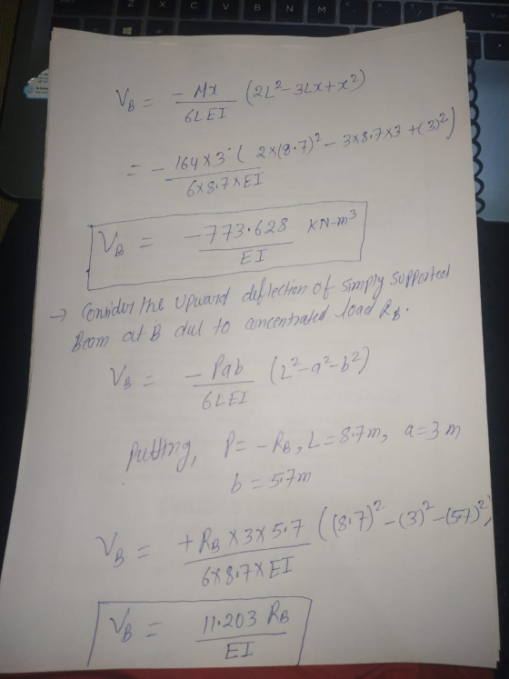
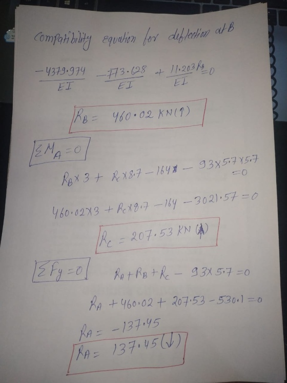
 P11.046 (Multistep) A W530 X 66 structural steel [E = 200 GPa) wide-flange shape is loaded and supported as shown in the figure. A uniformly distributed load of w = 66 kN/m is applied to the beam, causing the roller support at B to settle downward (i.e., displace downward) by d = 8 mm. Determine: (a) the reactions at supports A and B. (b) the maximum bending stress in the beam. Assume a = 5.5 m and b = 1.3...
The beam shown in the figure consists of a W360x19 structural steel wide-flange shape [E =...
 The beam shown in the figure consists of a W360x19 structural steel wide-flange shape [E = 200 GPa; = 225 ×106 mm": Mo-210 kN·m; w-90 kN/m, a _ 4 m, and b-5ml Me Determine the deformation at B due to the distributed load if the roller support at B is removed. 0.0972 m 0.1324 m 0.1444 m 0.1682 m 0.1599 m
The simply supported beam consists of a W410 × 60 structural steel wide-flange shape [E =...
 The simply supported beam consists of a W410 × 60 structural
steel wide-flange shape [E = 200 GPa; I = 216 ×
106 mm4]. For the loading shown, determine
the beam deflection at point C.
Assume P = 53 kN, w = 91 kN/m,
LAB = LBC = 1.7 m,
LDE = LCD=1.8 m,
MA = 197 kN-m.
200 GPa; I 216 x 100 mm ]. For the loading shown, determine the beam The simply supported beam consists of a...
The simply supported beam consists of a W410 × 60 structural
steel wide-flange shape [E = 200 GPa; I = 216 ×
106 mm4]. For the loading shown, determine
the beam deflection at point C.
Assume P = 53 kN, w = 91 kN/m,
LAB = LBC = 1.7 m,
LDE = LCD=1.8 m,
MA = 197 kN-m.
200 GPa; I 216 x 100 mm ]. For the loading shown, determine the beam The simply supported beam consists of a...
The simply supported beam consists of a W460 × 82 structural steel wide-flange shape [E =...
 The simply supported beam consists of a W460 × 82 structural
steel wide-flange shape [E = 200 GPa; I = 370 ×
106 mm4]. For the loading shown, determine
the beam deflection vC at point
C.
Assume P = 62 kN, w = 36 kN/m,
LAB = LBC = 3.9 m,
LCD = 1.9 m.
Chapter 10, Supplemental Question 053 Not Correct The samply supported beam cons sts o a W460 × 82 structural steel wide flange shape E :...
The simply supported beam consists of a W460 × 82 structural
steel wide-flange shape [E = 200 GPa; I = 370 ×
106 mm4]. For the loading shown, determine
the beam deflection vC at point
C.
Assume P = 62 kN, w = 36 kN/m,
LAB = LBC = 3.9 m,
LCD = 1.9 m.
Chapter 10, Supplemental Question 053 Not Correct The samply supported beam cons sts o a W460 × 82 structural steel wide flange shape E :...
Problem 2 Problem Statement A W310x33 wide-flange A36 steel beam is used for the application shown...
 Problem 2 Problem Statement A W310x33 wide-flange A36 steel beam is used for the application shown below. 10 kN 20 kN 20 KN 10 KN B --Im-eIm-e-Im -Im -Im-- Using beam theory, determine the maximum tensile and compressive bending stress you would expect in this problem and determine where those stresses would occur. Using the theory of elasticity finite element model available here, create a plot which verifies the stress distribution and the values predicted by beam theory at the...
P10.023 The simply supported beam consists of a W410 x 85 structural steel wide-flange shape [E...
 P10.023 The simply supported beam consists of a W410 x 85 structural steel wide-flange shape [E - 200 GPa? - 316 x 10 mm. For the loading shown, use discontinuity functions to computer (a) the slope of the beam at A, and (b) the deflection of the beam at midspan. Assume LA - LCD - 2.1 m, lec-3.0 m, w = 64 kN/m. Answers: (a) 0 L (b) ...The number of significant digits is set to estion Open Show Work
The simply supported beam consists of a W410 × 60 structural steel wide-flange shape [E = 200 GPa; I = 216 × 106 mm4]. F...
 The simply supported beam consists of a W410 × 60 structural
steel wide-flange shape [E = 200 GPa; I = 216 ×
106 mm4]. For the loading shown, determine
the beam deflection at point C.
Assume P = 72 kN, w = 60 kN/m,
LAB = LBC = 1.4 m,
LDE = LCD=1.4 m,
MA = 167 kN-m.
P10.048 Not Correct 216 x 106 mm41. For the loading shown, determine the beam deflection at point C The simply supported beam...
The simply supported beam consists of a W410 × 60 structural
steel wide-flange shape [E = 200 GPa; I = 216 ×
106 mm4]. For the loading shown, determine
the beam deflection at point C.
Assume P = 72 kN, w = 60 kN/m,
LAB = LBC = 1.4 m,
LDE = LCD=1.4 m,
MA = 167 kN-m.
P10.048 Not Correct 216 x 106 mm41. For the loading shown, determine the beam deflection at point C The simply supported beam...
A column with a wide-flange section has a flange width b = 400 mm , height...
 A column with a wide-flange section has a flange width
b = 400 mm , height h = 400 mm , web thickness
tw = 13 mm , and flange thickness
tf = 21 mm (Figure 1). Calculate the stresses at
a point 65 mm above the neutral axis if the section supports a
tensile normal force N = 3 kN at the centroid, shear force
V = 7.4 kN , and bending moment M = 4 kN⋅m as
shown...
A column with a wide-flange section has a flange width
b = 400 mm , height h = 400 mm , web thickness
tw = 13 mm , and flange thickness
tf = 21 mm (Figure 1). Calculate the stresses at
a point 65 mm above the neutral axis if the section supports a
tensile normal force N = 3 kN at the centroid, shear force
V = 7.4 kN , and bending moment M = 4 kN⋅m as
shown...
The beam shown will be constructed from a standard steel W-shape using an allowable bending stress...
 The beam shown will be constructed from a standard steel W-shape using an allowable bending stress of 150 MPa. Assume L=3.4 m, wA-44 kN/m and P-11 kN (a) Develop a list of four acceptable shapes that could be used for this beam. Include the most economical W310, W360, W410, and W460 shapes on the list of possibilities. (b) Select the most economical W shape for this beam. WA
For the Wide-Flange I-beam with distributed load as in figure below calculate: 1) the shear force...
 For the Wide-Flange I-beam with distributed load as in figure below calculate: 1) the shear force V(x) and the bending moment M(x) and plot the shear and bending moment diagrams 2) the maximum bending moment MMAX For the section of the beam with Mwax calculate for each of the points A and B shown in the figure: (a) the flexural stress og (b) the principal stresses 01, 02, 03 c) the principal stress angle Upi (d) the absolute maximum shear...
 P11.046 (Multistep) A W530 X 66 structural steel [E = 200 GPa) wide-flange shape is loaded and supported as shown in the figure. A uniformly distributed load of w = 66 kN/m is applied to the beam, causing the roller support at B to settle downward (i.e., displace downward) by d = 8 mm. Determine: (a) the reactions at supports A and B. (b) the maximum bending stress in the beam. Assume a = 5.5 m and b = 1.3...
 The beam shown in the figure consists of a W360x19 structural steel wide-flange shape [E = 200 GPa; = 225 ×106 mm": Mo-210 kN·m; w-90 kN/m, a _ 4 m, and b-5ml Me Determine the deformation at B due to the distributed load if the roller support at B is removed. 0.0972 m 0.1324 m 0.1444 m 0.1682 m 0.1599 m
 The simply supported beam consists of a W410 × 60 structural
steel wide-flange shape [E = 200 GPa; I = 216 ×
106 mm4]. For the loading shown, determine
the beam deflection at point C.
Assume P = 53 kN, w = 91 kN/m,
LAB = LBC = 1.7 m,
LDE = LCD=1.8 m,
MA = 197 kN-m.
200 GPa; I 216 x 100 mm ]. For the loading shown, determine the beam The simply supported beam consists of a...
The simply supported beam consists of a W410 × 60 structural
steel wide-flange shape [E = 200 GPa; I = 216 ×
106 mm4]. For the loading shown, determine
the beam deflection at point C.
Assume P = 53 kN, w = 91 kN/m,
LAB = LBC = 1.7 m,
LDE = LCD=1.8 m,
MA = 197 kN-m.
200 GPa; I 216 x 100 mm ]. For the loading shown, determine the beam The simply supported beam consists of a...
 The simply supported beam consists of a W460 × 82 structural
steel wide-flange shape [E = 200 GPa; I = 370 ×
106 mm4]. For the loading shown, determine
the beam deflection vC at point
C.
Assume P = 62 kN, w = 36 kN/m,
LAB = LBC = 3.9 m,
LCD = 1.9 m.
Chapter 10, Supplemental Question 053 Not Correct The samply supported beam cons sts o a W460 × 82 structural steel wide flange shape E :...
The simply supported beam consists of a W460 × 82 structural
steel wide-flange shape [E = 200 GPa; I = 370 ×
106 mm4]. For the loading shown, determine
the beam deflection vC at point
C.
Assume P = 62 kN, w = 36 kN/m,
LAB = LBC = 3.9 m,
LCD = 1.9 m.
Chapter 10, Supplemental Question 053 Not Correct The samply supported beam cons sts o a W460 × 82 structural steel wide flange shape E :...
 Problem 2 Problem Statement A W310x33 wide-flange A36 steel beam is used for the application shown below. 10 kN 20 kN 20 KN 10 KN B --Im-eIm-e-Im -Im -Im-- Using beam theory, determine the maximum tensile and compressive bending stress you would expect in this problem and determine where those stresses would occur. Using the theory of elasticity finite element model available here, create a plot which verifies the stress distribution and the values predicted by beam theory at the...
 P10.023 The simply supported beam consists of a W410 x 85 structural steel wide-flange shape [E - 200 GPa? - 316 x 10 mm. For the loading shown, use discontinuity functions to computer (a) the slope of the beam at A, and (b) the deflection of the beam at midspan. Assume LA - LCD - 2.1 m, lec-3.0 m, w = 64 kN/m. Answers: (a) 0 L (b) ...The number of significant digits is set to estion Open Show Work
 The simply supported beam consists of a W410 × 60 structural
steel wide-flange shape [E = 200 GPa; I = 216 ×
106 mm4]. For the loading shown, determine
the beam deflection at point C.
Assume P = 72 kN, w = 60 kN/m,
LAB = LBC = 1.4 m,
LDE = LCD=1.4 m,
MA = 167 kN-m.
P10.048 Not Correct 216 x 106 mm41. For the loading shown, determine the beam deflection at point C The simply supported beam...
The simply supported beam consists of a W410 × 60 structural
steel wide-flange shape [E = 200 GPa; I = 216 ×
106 mm4]. For the loading shown, determine
the beam deflection at point C.
Assume P = 72 kN, w = 60 kN/m,
LAB = LBC = 1.4 m,
LDE = LCD=1.4 m,
MA = 167 kN-m.
P10.048 Not Correct 216 x 106 mm41. For the loading shown, determine the beam deflection at point C The simply supported beam...
 A column with a wide-flange section has a flange width
b = 400 mm , height h = 400 mm , web thickness
tw = 13 mm , and flange thickness
tf = 21 mm (Figure 1). Calculate the stresses at
a point 65 mm above the neutral axis if the section supports a
tensile normal force N = 3 kN at the centroid, shear force
V = 7.4 kN , and bending moment M = 4 kN⋅m as
shown...
A column with a wide-flange section has a flange width
b = 400 mm , height h = 400 mm , web thickness
tw = 13 mm , and flange thickness
tf = 21 mm (Figure 1). Calculate the stresses at
a point 65 mm above the neutral axis if the section supports a
tensile normal force N = 3 kN at the centroid, shear force
V = 7.4 kN , and bending moment M = 4 kN⋅m as
shown...
 The beam shown will be constructed from a standard steel W-shape using an allowable bending stress of 150 MPa. Assume L=3.4 m, wA-44 kN/m and P-11 kN (a) Develop a list of four acceptable shapes that could be used for this beam. Include the most economical W310, W360, W410, and W460 shapes on the list of possibilities. (b) Select the most economical W shape for this beam. WA
 For the Wide-Flange I-beam with distributed load as in figure below calculate: 1) the shear force V(x) and the bending moment M(x) and plot the shear and bending moment diagrams 2) the maximum bending moment MMAX For the section of the beam with Mwax calculate for each of the points A and B shown in the figure: (a) the flexural stress og (b) the principal stresses 01, 02, 03 c) the principal stress angle Upi (d) the absolute maximum shear...
Most questions answered within 3 hours.
-
A business executive has the option to invest money in two
plans: Plan A guarantees that...
asked 1 hour ago -
Hello, can someone please help me answer this question?
How much heat is absorbed by a...
asked 1 hour ago -
. A marketing researcher conducted a survey of 25 shoppers
randomly selected at the local mall...
asked 2 hours ago -
Create an comprehensive response to the
following:
Antimicrobial agents work on a multitude of microbes (bacteria,...
asked 2 hours ago -
6.13 LAB: Step counter. Section 6.3.
A pedometer treats walking 2,000 steps as walking 1 mile....
asked 1 hour ago -
(14.2) A block of mass m = 10 kg riding on a frictionless
horizontal plane is...
asked 2 hours ago -
Use any search engine to search for articles about Starbucks
partnership with Tata Companies in India...
asked 2 hours ago -
Let’s say that for some reason Bank Excess Reserves suddenly
increase sharply. What effect would this...
asked 2 hours ago -
Given:
Curent Assets: $600,000
Total Assets: $2,600,000
Current Liabilities: $500,000
Total Liabilities: $1,700,000
What is the...
asked 2 hours ago -
1. What is a “Bankster”? What is insider trading? Why is it
illegal?
2. What is...
asked 2 hours ago -
A transverse wave on a cord is given by
D(x,t)=0.18sin(2.7x−61.0t), where Dand x are in m...
asked 2 hours ago -
ASSIGNMENT
ANSWER ANY TWO OF THE FOLLOWING IN 2-3 PARAGRAPHS OF EACH
QUESTION.
1: Where is...
asked 2 hours ago