
Homework Answers

Add Answer to:
lai). In the diode circuit below use iterative method (use at least 3 iterations) to find...
Part IIl: Diodes The Ideal-Diode Model a) For the circuit below, find ID and VD for the case VDD 5 V and R 10 k2. Assum...
 Part IIl: Diodes The Ideal-Diode Model a) For the circuit below, find ID and VD for the case VDD 5 V and R 10 k2. Assume that the diode has a voltage of 0.7 V at 1-mA current. Use (a) iteration and (b) the constant-voltage-drop model with VD 0.7 V 홍Yo b) Design the circuit below to provide an output voltage of 2.4 V. Assume that the diodes available have 0.7-V drop at 1 mA. +10 V Vo
Part IIl:...
Part IIl: Diodes The Ideal-Diode Model a) For the circuit below, find ID and VD for the case VDD 5 V and R 10 k2. Assume that the diode has a voltage of 0.7 V at 1-mA current. Use (a) iteration and (b) the constant-voltage-drop model with VD 0.7 V 홍Yo b) Design the circuit below to provide an output voltage of 2.4 V. Assume that the diodes available have 0.7-V drop at 1 mA. +10 V Vo
Part IIl:...
For the circuit below with the source peak Vs-10V and diode voltage Vpo-0.7V, the average output...
 For the circuit below with the source peak Vs-10V and diode voltage Vpo-0.7V, the average output voltage (Vo, avrthe peak current in the diode (omax! and PNV are: - 0.7 V + Rikos
For the double diode circuit shown in figure 2-1, answer the following questions. In Figure 2-1...
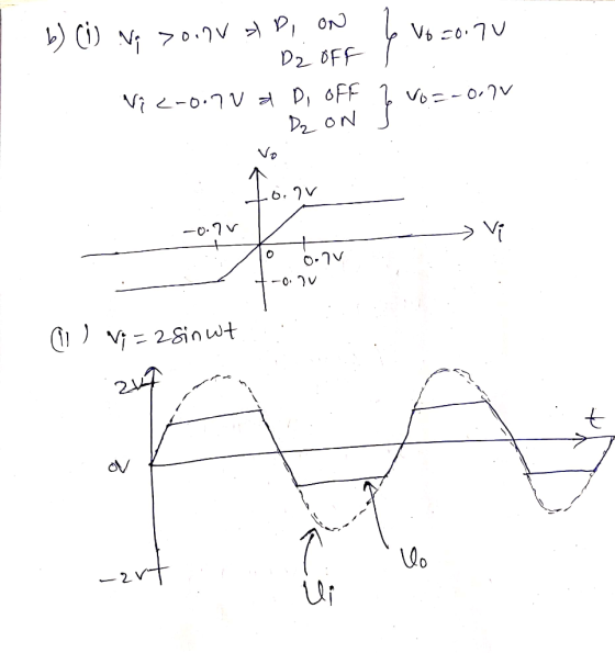
 For the double diode circuit shown in figure 2-1, answer the following questions. In Figure 2-1 a) (10pts) For the triangular wave input shown (Vin), sketch the output voltage (Vout) using the constant voltage drop model (CVD: Vo-0.7V). Be sure to note the voltage values on the y-axis of your Vout plot and show any equations you used to determine those values ime FEE 334: Spring 2019 Midterm b) (2pts) During the middle of the first time segment (when Vin...
The source voltage V1 = 10 V dc . Find the diode current using the iterative...
 The source voltage V1 = 10 V dc . Find the diode current using
the iterative technique discussed in clas s. Assume the diode has V
D =0.7 V at I D =2 mA and V T =25 mV . Perform two iterations only.
Then calculate the percentage difference between the I D and V D of
it eration 2 and the same values from iteration 1 using iteration 1
values as the reference.
out R1 Vout 1K W1
The source voltage V1 = 10 V dc . Find the diode current using
the iterative technique discussed in clas s. Assume the diode has V
D =0.7 V at I D =2 mA and V T =25 mV . Perform two iterations only.
Then calculate the percentage difference between the I D and V D of
it eration 2 and the same values from iteration 1 using iteration 1
values as the reference.
out R1 Vout 1K W1
4. In the diode circuit below diodes Day and Da2 are identical have a voltage of...
 4. In the diode circuit below diodes Day and Da2 are identical have a voltage of 0.7V at ImA current. The diodes Dbị and Db2 are identical and have 10 times the junction area of Dal. Also all diodes have n=2 and VI = 25mV. The circuit employs a supply current ISUPPLY=20mA. (a) Draw the i-v curve for diodes Da and D. Label axes and all relevant points. [8] (b) Find the value of Vout at nominal supply and no...
5. (15 Points) a. (8 points) Calculate the value of R to provide an output voltage of 3 V. Assume that the diodes have 0.7V drop at 1mA. b. (7 points) If the diode current changes to 4mA, what is the...
 5. (15 Points) a. (8 points) Calculate the value of R to provide
an output voltage of 3 V. Assume that the diodes have 0.7V drop at
1mA. b. (7 points) If the diode current changes to 4mA, what is the
new voltage drop across the four diodes?
+15 V
+15 V
5. (15 Points) a. (8 points) Calculate the value of R to provide
an output voltage of 3 V. Assume that the diodes have 0.7V drop at
1mA. b. (7 points) If the diode current changes to 4mA, what is the
new voltage drop across the four diodes?
+15 V
+15 V
2. In the circuit below, the forward voltage for each diode is 0.7 volts. Vdc 5V, R 10000, Vac 2c...
 2. In the circuit below, the forward voltage for each diode is 0.7 volts. Vdc 5V, R 10000, Vac 2cos(wt) Volts A. Show that the diodes will always be in forward. B. Find the voltage across the diodes C. Find the current through the diodes. D1 D2 D3 + Vac Vdc
2. In the circuit below, the forward voltage for each diode is 0.7 volts. Vdc 5V, R 10000, Vac 2cos(wt) Volts A. Show that the diodes will always be...
2. In the circuit below, the forward voltage for each diode is 0.7 volts. Vdc 5V, R 10000, Vac 2cos(wt) Volts A. Show that the diodes will always be in forward. B. Find the voltage across the diodes C. Find the current through the diodes. D1 D2 D3 + Vac Vdc
2. In the circuit below, the forward voltage for each diode is 0.7 volts. Vdc 5V, R 10000, Vac 2cos(wt) Volts A. Show that the diodes will always be...
Design a diode waveform shaping circuit that would have the above transfer function. You can use...
 Design a diode waveform shaping circuit that would have the
above transfer function. You can use PN junction diodes with VD0 =
0.7 V, DC voltage sources, and resistors in your design. You should
indicate the resistor values and the DC voltage sources’ values in
your design if you used any resistors or DC voltage sources. You
can use Zener diodes with different Vz values if you want, but you
do not have to.
Write the possible cases of the...
Design a diode waveform shaping circuit that would have the
above transfer function. You can use PN junction diodes with VD0 =
0.7 V, DC voltage sources, and resistors in your design. You should
indicate the resistor values and the DC voltage sources’ values in
your design if you used any resistors or DC voltage sources. You
can use Zener diodes with different Vz values if you want, but you
do not have to.
Write the possible cases of the...
Question 2 (6 points) D1 lkn Vout The circuit shown has Vs = 10 V. Assume...
 Question 2 (6 points) D1 lkn Vout The circuit shown has Vs = 10 V. Assume the diode has Vp = 0.7 V at ID = 2 mA and VI = 25 mV. Use the iterative technique to find the diode current (do two iterations only). Use the diode current found to determine the value of Vout: Vout = 9.300 V Vout = 9.262 V Vout = 9.296 V Vout = 9.189 V
Q.1. (a) For the following clipper circuit, plot the output versus time. The diode in the...
 Q.1. (a) For the following clipper circuit, plot the output versus time. The diode in the circuit has piecewise linear parameters Vs = 0.7 V and 1= 10 (10) R=1002 w DI VO 30 V + 10 V -30 vf (b) Sketch the output voltage V, versus time for the following circuit with the input voltage shown. Assume V = 0 and assume the RC time constant is large. (15) VA -H VO 20 V с Vg=5V = -20 V
 Part IIl: Diodes The Ideal-Diode Model a) For the circuit below, find ID and VD for the case VDD 5 V and R 10 k2. Assume that the diode has a voltage of 0.7 V at 1-mA current. Use (a) iteration and (b) the constant-voltage-drop model with VD 0.7 V 홍Yo b) Design the circuit below to provide an output voltage of 2.4 V. Assume that the diodes available have 0.7-V drop at 1 mA. +10 V Vo
Part IIl:...
Part IIl: Diodes The Ideal-Diode Model a) For the circuit below, find ID and VD for the case VDD 5 V and R 10 k2. Assume that the diode has a voltage of 0.7 V at 1-mA current. Use (a) iteration and (b) the constant-voltage-drop model with VD 0.7 V 홍Yo b) Design the circuit below to provide an output voltage of 2.4 V. Assume that the diodes available have 0.7-V drop at 1 mA. +10 V Vo
Part IIl:...
 For the circuit below with the source peak Vs-10V and diode voltage Vpo-0.7V, the average output voltage (Vo, avrthe peak current in the diode (omax! and PNV are: - 0.7 V + Rikos
 For the double diode circuit shown in figure 2-1, answer the following questions. In Figure 2-1 a) (10pts) For the triangular wave input shown (Vin), sketch the output voltage (Vout) using the constant voltage drop model (CVD: Vo-0.7V). Be sure to note the voltage values on the y-axis of your Vout plot and show any equations you used to determine those values ime FEE 334: Spring 2019 Midterm b) (2pts) During the middle of the first time segment (when Vin...
 The source voltage V1 = 10 V dc . Find the diode current using
the iterative technique discussed in clas s. Assume the diode has V
D =0.7 V at I D =2 mA and V T =25 mV . Perform two iterations only.
Then calculate the percentage difference between the I D and V D of
it eration 2 and the same values from iteration 1 using iteration 1
values as the reference.
out R1 Vout 1K W1
The source voltage V1 = 10 V dc . Find the diode current using
the iterative technique discussed in clas s. Assume the diode has V
D =0.7 V at I D =2 mA and V T =25 mV . Perform two iterations only.
Then calculate the percentage difference between the I D and V D of
it eration 2 and the same values from iteration 1 using iteration 1
values as the reference.
out R1 Vout 1K W1
 4. In the diode circuit below diodes Day and Da2 are identical have a voltage of 0.7V at ImA current. The diodes Dbị and Db2 are identical and have 10 times the junction area of Dal. Also all diodes have n=2 and VI = 25mV. The circuit employs a supply current ISUPPLY=20mA. (a) Draw the i-v curve for diodes Da and D. Label axes and all relevant points. [8] (b) Find the value of Vout at nominal supply and no...
 5. (15 Points) a. (8 points) Calculate the value of R to provide
an output voltage of 3 V. Assume that the diodes have 0.7V drop at
1mA. b. (7 points) If the diode current changes to 4mA, what is the
new voltage drop across the four diodes?
+15 V
+15 V
5. (15 Points) a. (8 points) Calculate the value of R to provide
an output voltage of 3 V. Assume that the diodes have 0.7V drop at
1mA. b. (7 points) If the diode current changes to 4mA, what is the
new voltage drop across the four diodes?
+15 V
+15 V
 2. In the circuit below, the forward voltage for each diode is 0.7 volts. Vdc 5V, R 10000, Vac 2cos(wt) Volts A. Show that the diodes will always be in forward. B. Find the voltage across the diodes C. Find the current through the diodes. D1 D2 D3 + Vac Vdc
2. In the circuit below, the forward voltage for each diode is 0.7 volts. Vdc 5V, R 10000, Vac 2cos(wt) Volts A. Show that the diodes will always be...
2. In the circuit below, the forward voltage for each diode is 0.7 volts. Vdc 5V, R 10000, Vac 2cos(wt) Volts A. Show that the diodes will always be in forward. B. Find the voltage across the diodes C. Find the current through the diodes. D1 D2 D3 + Vac Vdc
2. In the circuit below, the forward voltage for each diode is 0.7 volts. Vdc 5V, R 10000, Vac 2cos(wt) Volts A. Show that the diodes will always be...
 Design a diode waveform shaping circuit that would have the
above transfer function. You can use PN junction diodes with VD0 =
0.7 V, DC voltage sources, and resistors in your design. You should
indicate the resistor values and the DC voltage sources’ values in
your design if you used any resistors or DC voltage sources. You
can use Zener diodes with different Vz values if you want, but you
do not have to.
Write the possible cases of the...
Design a diode waveform shaping circuit that would have the
above transfer function. You can use PN junction diodes with VD0 =
0.7 V, DC voltage sources, and resistors in your design. You should
indicate the resistor values and the DC voltage sources’ values in
your design if you used any resistors or DC voltage sources. You
can use Zener diodes with different Vz values if you want, but you
do not have to.
Write the possible cases of the...
 Question 2 (6 points) D1 lkn Vout The circuit shown has Vs = 10 V. Assume the diode has Vp = 0.7 V at ID = 2 mA and VI = 25 mV. Use the iterative technique to find the diode current (do two iterations only). Use the diode current found to determine the value of Vout: Vout = 9.300 V Vout = 9.262 V Vout = 9.296 V Vout = 9.189 V
 Q.1. (a) For the following clipper circuit, plot the output versus time. The diode in the circuit has piecewise linear parameters Vs = 0.7 V and 1= 10 (10) R=1002 w DI VO 30 V + 10 V -30 vf (b) Sketch the output voltage V, versus time for the following circuit with the input voltage shown. Assume V = 0 and assume the RC time constant is large. (15) VA -H VO 20 V с Vg=5V = -20 V
Most questions answered within 3 hours.
-
Given the following table of high speed internet access vs.
annual home income:
Home Income
%...
asked 13 minutes ago -
A baseball batter hits a 0.145kg baseball straight up into the
air. The baseball leaves the...
asked 45 minutes ago -
An FM modulator is tested using
single-tone baseband signal with frequency of 50kHz and a sprectrum...
asked 1 hour ago -
Write the ionic equations for the first stage of salts
hydrolysis.
Anion, Cation?
Na2S
NiSO4
K2SO4...
asked 2 hours ago -
suppose there is a normally distributed population with a mean of
250 and a standard deviation...
asked 3 hours ago -
Question Three
Suppose you as project manager are using the Waterfall
development methodology on a large...
asked 4 hours ago -
Which statement is not true about welfare in Canada?
A.Benefits typically vary based on one's ability...
asked 4 hours ago -
Please help me with FLOWCHART and UML diagram for class,
thank you!
#include <iostream>
#include <fstream>...
asked 5 hours ago -
3. Describe the “logic circuit” of the Lac operon. Which
proteins are bound or not to...
asked 5 hours ago -
Ayesha’s adjusted gross income is $60,000 in 2019. She donated a
piece of artwork with a...
asked 5 hours ago -
For Dijkstra’s shortest path algorithm:
a. Give the Big-O time for Dijkstra’s shortest path algorithm
and...
asked 5 hours ago -
Phosphorus violates the 'octet rule' in biological molecules,
forming more covalent bonds than expected based on...
asked 6 hours ago