
Homework Answers


Add Answer to:
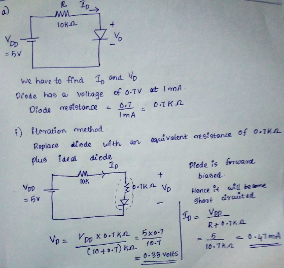
Part IIl: Diodes The Ideal-Diode Model a) For the circuit below, find ID and VD for the case VDD 5 V and R 10 k2. Assum...
lai). In the diode circuit below use iterative method (use at least 3 iterations) to find...
 lai). In the diode circuit below use iterative method (use at least 3 iterations) to find the diode voltage and current, if VDD=2.0 V, R= 1 KO2, the diode has Is - 10e- 15 A Find diode voltage and current using constant 0.7 V drop model. comment on the results of (i) and (ii) (iii) ang DV. b. Both diodes in the circuit below are rated 0.7V, 1mA. R=1KN Sketch vo vs vi If vi = 2sinot, on the same...
2. For the circuit shown in Figure 4, assume the diode can be modelled by a...
 2. For the circuit shown in Figure 4, assume the diode can be modelled by a Constant- Voltage Drop (CVD) (VD[on) = 0.7 V) for d.c analysis. 10 mA 5502 Zc = 0 int) DV D3 D2 V 100 sin(wt) mV vo(t) 1k 12 } 3k 22 Figure 4 (a) Determine the diode d.c current loi, Ioz, 103, Io and V. Check your assumptions. (b) Determine the output ac current, id and voltage, vd (c) Determine the output total current,...
The diode in the circuit below has a saturation current Is-10-13 A and n=1. Its ID-VD...
 The diode in the circuit below has a saturation current Is-10-13 A and n=1. Its ID-VD curve is illustrated below for your convenience. Problem 2 a) Using the graphical method, determine the value of R that would result in a diode current Ip -4mA. What is the resulting voltage Vp? b) With R as calculated above, a sinusoidal signal v, 100 sin(cot) mV is superimposed on the DC source. Draw the small signal model and find the output voltage across...
Exercise 18.20: Modify the circuit below by replacing R by a pair of diodes connected in parallef in opposite directions. For L+-L-12 V, R2-R-10 kQ, C = 0.1 μF and the diode voltage as a constant...
 Exercise 18.20: Modify the circuit below by replacing R by a pair of diodes connected in parallef in opposite directions. For L+-L-12 V, R2-R-10 kQ, C = 0.1 μF and the diode voltage as a constant denoted VD, find an expression for frequency as a function of Vp. fV 0.7 V at 25 with a TC of-2mV/PC, find the frequency at 0, 25°, 50° and 1009 Note that the output of this circuit can be sent to a remotely connected...
do appreciate the process in details and neat (b) The circuit shown in Figure 2 utilizes two diodes, Di and D2, a R, resistor R1 = 10 Ω. Assume a piecewise linear (PWL) model for the diode that ha...
 do appreciate the process in details and neat
(b) The circuit shown in Figure 2 utilizes two diodes, Di and D2, a R, resistor R1 = 10 Ω. Assume a piecewise linear (PWL) model for the diode that has VD 07 and r-5 Ω. Draw the output voltage, vo, as function of the input voltage, Vin, characteristics of this circuit at point assuming the input voltage has a peak-to-peak voltage of 3 Volt. There is no need to draw the...
do appreciate the process in details and neat
(b) The circuit shown in Figure 2 utilizes two diodes, Di and D2, a R, resistor R1 = 10 Ω. Assume a piecewise linear (PWL) model for the diode that has VD 07 and r-5 Ω. Draw the output voltage, vo, as function of the input voltage, Vin, characteristics of this circuit at point assuming the input voltage has a peak-to-peak voltage of 3 Volt. There is no need to draw the...
1. (30 points) Diodes in the circuit below have the cut-in voltage V, -0.7 V. Find...
 1. (30 points) Diodes in the circuit below have the cut-in voltage V, -0.7 V. Find the output Vif a) (15 points) 7=1 mA. b) (15 points) 7 = 2 mA. Hint to immediately identify the operating mode (regime) of one diode: where does / flow? § 2 = 2 kB D {R = 5
Find the operational state of diodes shown in the figure given below. Assume non-ideal diode model...
 Find the operational state of diodes shown in the figure given below. Assume non-ideal diode model with constant voltage drop Von = 0.7V. to2 4V (A) D, -ON,D2 - ON (B) D2 - ON,D2 - OFF (C) D2 - OFF,D2 - ON (D) D2 - OFF,D2 - OFF
Question 1 (4 Marks) 1) In the circuit shown, find / and V, using the ideal...
 Question 1 (4 Marks) 1) In the circuit shown, find / and V, using the ideal diode model. 240 2) Consider the given circuit a. Design R for an output voltage of 1.5 V. Assume identical diodes with land Is 104 A. b. Explain why the circuit could be used for supply noise regulation
This is a Diode constant voltage model - clipping circuits Please explain steps as you solve....
 This is a Diode constant voltage model - clipping
circuits
Please explain steps as you solve. Thank you very much for
your help. please ask if there is anything not clear about the
problem
W (a) For the circuit shown below use the constant voltage diode model (Vp=0.7 V), and find the state of diodes D, and D2 (ie. ON or OFF) and determine the voltage and the current for each. 32k2 OV 5 mA 103=_ ; VD3= 104= ;...
This is a Diode constant voltage model - clipping
circuits
Please explain steps as you solve. Thank you very much for
your help. please ask if there is anything not clear about the
problem
W (a) For the circuit shown below use the constant voltage diode model (Vp=0.7 V), and find the state of diodes D, and D2 (ie. ON or OFF) and determine the voltage and the current for each. 32k2 OV 5 mA 103=_ ; VD3= 104= ;...
1. The below circuit utilizes four identical diodes having Is=10-16 A and V1=26mV. If a current...
 1. The below circuit utilizes four identical diodes having Is=10-16 A and V1=26mV. If a current of 1 mA is drawn away from an output terminal by a load, what is the change in output voltage? Assume that a diode will have a voltage drop of 0.75V when 15V voltage is applied to a below circuit and no load was connected, as shown below (20 pts) +15V R ovo
 lai). In the diode circuit below use iterative method (use at least 3 iterations) to find the diode voltage and current, if VDD=2.0 V, R= 1 KO2, the diode has Is - 10e- 15 A Find diode voltage and current using constant 0.7 V drop model. comment on the results of (i) and (ii) (iii) ang DV. b. Both diodes in the circuit below are rated 0.7V, 1mA. R=1KN Sketch vo vs vi If vi = 2sinot, on the same...
 2. For the circuit shown in Figure 4, assume the diode can be modelled by a Constant- Voltage Drop (CVD) (VD[on) = 0.7 V) for d.c analysis. 10 mA 5502 Zc = 0 int) DV D3 D2 V 100 sin(wt) mV vo(t) 1k 12 } 3k 22 Figure 4 (a) Determine the diode d.c current loi, Ioz, 103, Io and V. Check your assumptions. (b) Determine the output ac current, id and voltage, vd (c) Determine the output total current,...
 The diode in the circuit below has a saturation current Is-10-13 A and n=1. Its ID-VD curve is illustrated below for your convenience. Problem 2 a) Using the graphical method, determine the value of R that would result in a diode current Ip -4mA. What is the resulting voltage Vp? b) With R as calculated above, a sinusoidal signal v, 100 sin(cot) mV is superimposed on the DC source. Draw the small signal model and find the output voltage across...
 Exercise 18.20: Modify the circuit below by replacing R by a pair of diodes connected in parallef in opposite directions. For L+-L-12 V, R2-R-10 kQ, C = 0.1 μF and the diode voltage as a constant denoted VD, find an expression for frequency as a function of Vp. fV 0.7 V at 25 with a TC of-2mV/PC, find the frequency at 0, 25°, 50° and 1009 Note that the output of this circuit can be sent to a remotely connected...
 do appreciate the process in details and neat
(b) The circuit shown in Figure 2 utilizes two diodes, Di and D2, a R, resistor R1 = 10 Ω. Assume a piecewise linear (PWL) model for the diode that has VD 07 and r-5 Ω. Draw the output voltage, vo, as function of the input voltage, Vin, characteristics of this circuit at point assuming the input voltage has a peak-to-peak voltage of 3 Volt. There is no need to draw the...
do appreciate the process in details and neat
(b) The circuit shown in Figure 2 utilizes two diodes, Di and D2, a R, resistor R1 = 10 Ω. Assume a piecewise linear (PWL) model for the diode that has VD 07 and r-5 Ω. Draw the output voltage, vo, as function of the input voltage, Vin, characteristics of this circuit at point assuming the input voltage has a peak-to-peak voltage of 3 Volt. There is no need to draw the...
 1. (30 points) Diodes in the circuit below have the cut-in voltage V, -0.7 V. Find the output Vif a) (15 points) 7=1 mA. b) (15 points) 7 = 2 mA. Hint to immediately identify the operating mode (regime) of one diode: where does / flow? § 2 = 2 kB D {R = 5
 Find the operational state of diodes shown in the figure given below. Assume non-ideal diode model with constant voltage drop Von = 0.7V. to2 4V (A) D, -ON,D2 - ON (B) D2 - ON,D2 - OFF (C) D2 - OFF,D2 - ON (D) D2 - OFF,D2 - OFF
 Question 1 (4 Marks) 1) In the circuit shown, find / and V, using the ideal diode model. 240 2) Consider the given circuit a. Design R for an output voltage of 1.5 V. Assume identical diodes with land Is 104 A. b. Explain why the circuit could be used for supply noise regulation
 This is a Diode constant voltage model - clipping
circuits
Please explain steps as you solve. Thank you very much for
your help. please ask if there is anything not clear about the
problem
W (a) For the circuit shown below use the constant voltage diode model (Vp=0.7 V), and find the state of diodes D, and D2 (ie. ON or OFF) and determine the voltage and the current for each. 32k2 OV 5 mA 103=_ ; VD3= 104= ;...
This is a Diode constant voltage model - clipping
circuits
Please explain steps as you solve. Thank you very much for
your help. please ask if there is anything not clear about the
problem
W (a) For the circuit shown below use the constant voltage diode model (Vp=0.7 V), and find the state of diodes D, and D2 (ie. ON or OFF) and determine the voltage and the current for each. 32k2 OV 5 mA 103=_ ; VD3= 104= ;...
 1. The below circuit utilizes four identical diodes having Is=10-16 A and V1=26mV. If a current of 1 mA is drawn away from an output terminal by a load, what is the change in output voltage? Assume that a diode will have a voltage drop of 0.75V when 15V voltage is applied to a below circuit and no load was connected, as shown below (20 pts) +15V R ovo
Most questions answered within 3 hours.
-
You have a 825.3 mL sample of 2.754 M HA (Ka =
4.49⋅10−4). Calculate the pH...
asked 34 minutes ago -
The blues made its way into many kinds of music. Eric Clapton,
The Beatles, and Elvis...
asked 2 hours ago -
8. A wave in a string has a wave function given by: y (x, t) =...
asked 1 hour ago -
If you’re standing at the bottom of a hill and asked to evaluate
it while being...
asked 3 hours ago -
1. Which region has taken the lead in the world of
e-waste handling?
a) European Union...
asked 3 hours ago -
A 8.15- g bullet from a 9-mm pistol has a velocity of 366.0 m/s.
It strikes...
asked 4 hours ago -
The outstanding bonds of Alpha Extracts have a yield to maturity
of 7.4 percent and a...
asked 4 hours ago -
The Problem: The Case of the Harmonizing Vacations
Your CEO is exploring partnering with a European...
asked 6 hours ago -
A chemical equation is balanced by adding coefficients in front
of some formulas so that the...
asked 6 hours ago -
From the literature (reference your sources): What are the
lattice parameters of calcite and aragonite? Why...
asked 6 hours ago -
Your system is rejecting the question am asking which is
preceded by a case study. It...
asked 7 hours ago -
3. On January 2, 2000, Larry creates a trust with himself as
trustee. Larry as trustee...
asked 7 hours ago