
Homework Answers


Add Answer to:
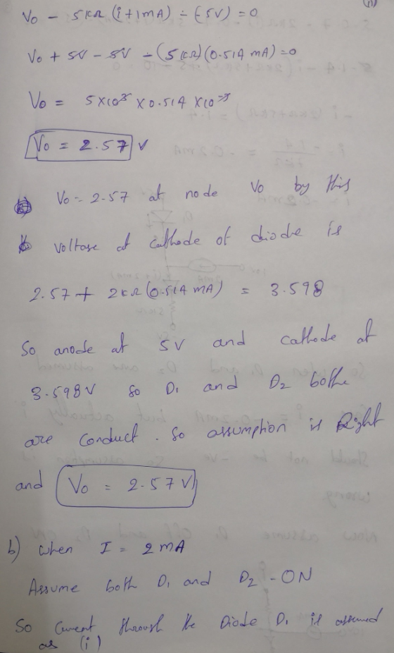
1. (30 points) Diodes in the circuit below have the cut-in voltage V, -0.7 V. Find...
Part IIl: Diodes The Ideal-Diode Model a) For the circuit below, find ID and VD for the case VDD 5 V and R 10 k2. Assum...
 Part IIl: Diodes The Ideal-Diode Model a) For the circuit below, find ID and VD for the case VDD 5 V and R 10 k2. Assume that the diode has a voltage of 0.7 V at 1-mA current. Use (a) iteration and (b) the constant-voltage-drop model with VD 0.7 V 홍Yo b) Design the circuit below to provide an output voltage of 2.4 V. Assume that the diodes available have 0.7-V drop at 1 mA. +10 V Vo
Part IIl:...
Part IIl: Diodes The Ideal-Diode Model a) For the circuit below, find ID and VD for the case VDD 5 V and R 10 k2. Assume that the diode has a voltage of 0.7 V at 1-mA current. Use (a) iteration and (b) the constant-voltage-drop model with VD 0.7 V 홍Yo b) Design the circuit below to provide an output voltage of 2.4 V. Assume that the diodes available have 0.7-V drop at 1 mA. +10 V Vo
Part IIl:...
3. (25 points) Find Ip and Ire for R 5k. Cut-in voltage for both diodes is...
 3. (25 points) Find Ip and Ire for R 5k. Cut-in voltage for both diodes is Vy = 0.6 V. Work out at least one scenario with 'wrong assumption for the operating mode of the diodes (excluding the obvious regime 'both di odes oft) 110 alin
4. In the diode circuit below diodes Day and Da2 are identical have a voltage of...
 4. In the diode circuit below diodes Day and Da2 are identical have a voltage of 0.7V at ImA current. The diodes Dbị and Db2 are identical and have 10 times the junction area of Dal. Also all diodes have n=2 and VI = 25mV. The circuit employs a supply current ISUPPLY=20mA. (a) Draw the i-v curve for diodes Da and D. Label axes and all relevant points. [8] (b) Find the value of Vout at nominal supply and no...
5. (15 Points) a. (8 points) Calculate the value of R to provide an output voltage of 3 V. Assume that the diodes have 0.7V drop at 1mA. b. (7 points) If the diode current changes to 4mA, what is the...
 5. (15 Points) a. (8 points) Calculate the value of R to provide
an output voltage of 3 V. Assume that the diodes have 0.7V drop at
1mA. b. (7 points) If the diode current changes to 4mA, what is the
new voltage drop across the four diodes?
+15 V
+15 V
5. (15 Points) a. (8 points) Calculate the value of R to provide
an output voltage of 3 V. Assume that the diodes have 0.7V drop at
1mA. b. (7 points) If the diode current changes to 4mA, what is the
new voltage drop across the four diodes?
+15 V
+15 V
2. In the circuit below, the forward voltage for each diode is 0.7 volts. Vdc 5V, R 10000, Vac 2c...
 2. In the circuit below, the forward voltage for each diode is 0.7 volts. Vdc 5V, R 10000, Vac 2cos(wt) Volts A. Show that the diodes will always be in forward. B. Find the voltage across the diodes C. Find the current through the diodes. D1 D2 D3 + Vac Vdc
2. In the circuit below, the forward voltage for each diode is 0.7 volts. Vdc 5V, R 10000, Vac 2cos(wt) Volts A. Show that the diodes will always be...
2. In the circuit below, the forward voltage for each diode is 0.7 volts. Vdc 5V, R 10000, Vac 2cos(wt) Volts A. Show that the diodes will always be in forward. B. Find the voltage across the diodes C. Find the current through the diodes. D1 D2 D3 + Vac Vdc
2. In the circuit below, the forward voltage for each diode is 0.7 volts. Vdc 5V, R 10000, Vac 2cos(wt) Volts A. Show that the diodes will always be...
Consider the circuit shown in Figure 1. Assume that the diodes have an exponen Question 21 tial i-v characteristic....
 Consider the circuit shown in Figure 1. Assume that the diodes have an exponen Question 21 tial i-v characteristic. Diode D1 has 10 times the junction area of D2, i.e. Isı = 10Is2. Determine the value of voltage V indicated in the figure. The circuit operates at room temperature, i.e. the value of the thermal voltage is Vr = 26 mV 10 mA 3 mA Fig. 1 O+V
Consider the circuit shown in Figure 1. Assume that the diodes have...
Consider the circuit shown in Figure 1. Assume that the diodes have an exponen Question 21 tial i-v characteristic. Diode D1 has 10 times the junction area of D2, i.e. Isı = 10Is2. Determine the value of voltage V indicated in the figure. The circuit operates at room temperature, i.e. the value of the thermal voltage is Vr = 26 mV 10 mA 3 mA Fig. 1 O+V
Consider the circuit shown in Figure 1. Assume that the diodes have...
Exercise 18.20: Modify the circuit below by replacing R by a pair of diodes connected in parallef in opposite directions. For L+-L-12 V, R2-R-10 kQ, C = 0.1 μF and the diode voltage as a constant...
 Exercise 18.20: Modify the circuit below by replacing R by a pair of diodes connected in parallef in opposite directions. For L+-L-12 V, R2-R-10 kQ, C = 0.1 μF and the diode voltage as a constant denoted VD, find an expression for frequency as a function of Vp. fV 0.7 V at 25 with a TC of-2mV/PC, find the frequency at 0, 25°, 50° and 1009 Note that the output of this circuit can be sent to a remotely connected...
1. The below circuit utilizes four identical diodes having Is=10-16 A and V1=26mV. If a current...
 1. The below circuit utilizes four identical diodes having Is=10-16 A and V1=26mV. If a current of 1 mA is drawn away from an output terminal by a load, what is the change in output voltage? Assume that a diode will have a voltage drop of 0.75V when 15V voltage is applied to a below circuit and no load was connected, as shown below (20 pts) +15V R ovo
QUESTION 14 If practical diodes are used in the bridge rectifier circuit thown below, the peak inverse voltage, PIV for the diode D1 will be equal to2markt) Di Ds oan PumB Ri. D2 D4 Vplout)-0.7 v...
 QUESTION 14 If practical diodes are used in the bridge rectifier circuit thown below, the peak inverse voltage, PIV for the diode D1 will be equal to2markt) Di Ds oan PumB Ri. D2 D4 Vplout)-0.7 volts Vplsec)-0.7 volts Vplot2+0.7 volts Vplout
QUESTION 14 If practical diodes are used in the bridge rectifier circuit thown below, the peak inverse voltage, PIV for the diode D1 will be equal to2markt) Di Ds oan PumB Ri. D2 D4 Vplout)-0.7 volts Vplsec)-0.7 volts Vplot2+0.7...
QUESTION 14 If practical diodes are used in the bridge rectifier circuit thown below, the peak inverse voltage, PIV for the diode D1 will be equal to2markt) Di Ds oan PumB Ri. D2 D4 Vplout)-0.7 volts Vplsec)-0.7 volts Vplot2+0.7 volts Vplout
QUESTION 14 If practical diodes are used in the bridge rectifier circuit thown below, the peak inverse voltage, PIV for the diode D1 will be equal to2markt) Di Ds oan PumB Ri. D2 D4 Vplout)-0.7 volts Vplsec)-0.7 volts Vplot2+0.7...
*4.57 Consider the voltage-regulator circuit shown in Fig. P4.57. The value of R is selected to...
 *4.57 Consider the voltage-regulator circuit shown in Fig. P4.57. The value of R is selected to obtain an output voltage Vo (across the diode) of 0.7 V. Figure P4.57 (a) Use the diode small-signal model to show that the change in output voltage corresponding to a change of 1 V in Vt is AV AV: = v* +-0.7 V+ V++V, -0.7 This quantity is known as the line regulation and is usually expressed in mV/V. (b) Generalize the expression above...
 Part IIl: Diodes The Ideal-Diode Model a) For the circuit below, find ID and VD for the case VDD 5 V and R 10 k2. Assume that the diode has a voltage of 0.7 V at 1-mA current. Use (a) iteration and (b) the constant-voltage-drop model with VD 0.7 V 홍Yo b) Design the circuit below to provide an output voltage of 2.4 V. Assume that the diodes available have 0.7-V drop at 1 mA. +10 V Vo
Part IIl:...
Part IIl: Diodes The Ideal-Diode Model a) For the circuit below, find ID and VD for the case VDD 5 V and R 10 k2. Assume that the diode has a voltage of 0.7 V at 1-mA current. Use (a) iteration and (b) the constant-voltage-drop model with VD 0.7 V 홍Yo b) Design the circuit below to provide an output voltage of 2.4 V. Assume that the diodes available have 0.7-V drop at 1 mA. +10 V Vo
Part IIl:...
 3. (25 points) Find Ip and Ire for R 5k. Cut-in voltage for both diodes is Vy = 0.6 V. Work out at least one scenario with 'wrong assumption for the operating mode of the diodes (excluding the obvious regime 'both di odes oft) 110 alin
 4. In the diode circuit below diodes Day and Da2 are identical have a voltage of 0.7V at ImA current. The diodes Dbị and Db2 are identical and have 10 times the junction area of Dal. Also all diodes have n=2 and VI = 25mV. The circuit employs a supply current ISUPPLY=20mA. (a) Draw the i-v curve for diodes Da and D. Label axes and all relevant points. [8] (b) Find the value of Vout at nominal supply and no...
 5. (15 Points) a. (8 points) Calculate the value of R to provide
an output voltage of 3 V. Assume that the diodes have 0.7V drop at
1mA. b. (7 points) If the diode current changes to 4mA, what is the
new voltage drop across the four diodes?
+15 V
+15 V
5. (15 Points) a. (8 points) Calculate the value of R to provide
an output voltage of 3 V. Assume that the diodes have 0.7V drop at
1mA. b. (7 points) If the diode current changes to 4mA, what is the
new voltage drop across the four diodes?
+15 V
+15 V
 2. In the circuit below, the forward voltage for each diode is 0.7 volts. Vdc 5V, R 10000, Vac 2cos(wt) Volts A. Show that the diodes will always be in forward. B. Find the voltage across the diodes C. Find the current through the diodes. D1 D2 D3 + Vac Vdc
2. In the circuit below, the forward voltage for each diode is 0.7 volts. Vdc 5V, R 10000, Vac 2cos(wt) Volts A. Show that the diodes will always be...
2. In the circuit below, the forward voltage for each diode is 0.7 volts. Vdc 5V, R 10000, Vac 2cos(wt) Volts A. Show that the diodes will always be in forward. B. Find the voltage across the diodes C. Find the current through the diodes. D1 D2 D3 + Vac Vdc
2. In the circuit below, the forward voltage for each diode is 0.7 volts. Vdc 5V, R 10000, Vac 2cos(wt) Volts A. Show that the diodes will always be...
 Consider the circuit shown in Figure 1. Assume that the diodes have an exponen Question 21 tial i-v characteristic. Diode D1 has 10 times the junction area of D2, i.e. Isı = 10Is2. Determine the value of voltage V indicated in the figure. The circuit operates at room temperature, i.e. the value of the thermal voltage is Vr = 26 mV 10 mA 3 mA Fig. 1 O+V
Consider the circuit shown in Figure 1. Assume that the diodes have...
Consider the circuit shown in Figure 1. Assume that the diodes have an exponen Question 21 tial i-v characteristic. Diode D1 has 10 times the junction area of D2, i.e. Isı = 10Is2. Determine the value of voltage V indicated in the figure. The circuit operates at room temperature, i.e. the value of the thermal voltage is Vr = 26 mV 10 mA 3 mA Fig. 1 O+V
Consider the circuit shown in Figure 1. Assume that the diodes have...
 Exercise 18.20: Modify the circuit below by replacing R by a pair of diodes connected in parallef in opposite directions. For L+-L-12 V, R2-R-10 kQ, C = 0.1 μF and the diode voltage as a constant denoted VD, find an expression for frequency as a function of Vp. fV 0.7 V at 25 with a TC of-2mV/PC, find the frequency at 0, 25°, 50° and 1009 Note that the output of this circuit can be sent to a remotely connected...
 1. The below circuit utilizes four identical diodes having Is=10-16 A and V1=26mV. If a current of 1 mA is drawn away from an output terminal by a load, what is the change in output voltage? Assume that a diode will have a voltage drop of 0.75V when 15V voltage is applied to a below circuit and no load was connected, as shown below (20 pts) +15V R ovo
 QUESTION 14 If practical diodes are used in the bridge rectifier circuit thown below, the peak inverse voltage, PIV for the diode D1 will be equal to2markt) Di Ds oan PumB Ri. D2 D4 Vplout)-0.7 volts Vplsec)-0.7 volts Vplot2+0.7 volts Vplout
QUESTION 14 If practical diodes are used in the bridge rectifier circuit thown below, the peak inverse voltage, PIV for the diode D1 will be equal to2markt) Di Ds oan PumB Ri. D2 D4 Vplout)-0.7 volts Vplsec)-0.7 volts Vplot2+0.7...
QUESTION 14 If practical diodes are used in the bridge rectifier circuit thown below, the peak inverse voltage, PIV for the diode D1 will be equal to2markt) Di Ds oan PumB Ri. D2 D4 Vplout)-0.7 volts Vplsec)-0.7 volts Vplot2+0.7 volts Vplout
QUESTION 14 If practical diodes are used in the bridge rectifier circuit thown below, the peak inverse voltage, PIV for the diode D1 will be equal to2markt) Di Ds oan PumB Ri. D2 D4 Vplout)-0.7 volts Vplsec)-0.7 volts Vplot2+0.7...
 *4.57 Consider the voltage-regulator circuit shown in Fig. P4.57. The value of R is selected to obtain an output voltage Vo (across the diode) of 0.7 V. Figure P4.57 (a) Use the diode small-signal model to show that the change in output voltage corresponding to a change of 1 V in Vt is AV AV: = v* +-0.7 V+ V++V, -0.7 This quantity is known as the line regulation and is usually expressed in mV/V. (b) Generalize the expression above...
Most questions answered within 3 hours.
-
Compare the Forfaiting and Factoring forms of export
financing
asked 1 minute ago -
Europe in the 19th century was not dominated by:
a. the scientific quest
b. economic collectivism...
asked 9 minutes ago -
"The economic theory suggests that consumers will not shop at or
spend their money with a...
asked 14 minutes ago -
In your opinion, which provides the most benefit to an
organization, a budget or the budgeting...
asked 24 minutes ago -
What features are centralized in your web application by master
pages? How are master pages implemented...
asked 21 minutes ago -
Write the expression for the molecular wavefunction of (i) a
s-pz sigma bond and (ii) a...
asked 29 minutes ago -
It costs Crane Company $28 of variable costs and $10.00 of
allocated fixed costs to produce...
asked 43 minutes ago -
Explain the following basis of electron configuration i) the
electron affinity of S is +200kJ mol-1
asked 52 minutes ago -
Determine the pH of a 0.10 M
CH3NH3Cl solution.
(Kb
(CH3NH2) = 4.4 x 10⁻⁴)
2.18...
asked 1 hour ago -
Asolid metal sphere with radius 0.470 m carries a net charge of
0.200 nC .
Part...
asked 57 minutes ago -
Determine the pH of a 0.0500 M KBr solution (using activity
coefficients when needed)
( please...
asked 58 minutes ago -
Bender's skateboards have the following manufacturing
expenses:
Direct Materials: $10/unit
Direct Labor: $8/unit
Rent: $10,000/month
Depreciation:...
asked 1 hour ago