
Homework Answers
Add Answer to:
*4.57 Consider the voltage-regulator circuit shown in Fig. P4.57. The value of R is selected to...
Part IIl: Diodes The Ideal-Diode Model a) For the circuit below, find ID and VD for the case VDD 5 V and R 10 k2. Assum...
 Part IIl: Diodes The Ideal-Diode Model a) For the circuit below, find ID and VD for the case VDD 5 V and R 10 k2. Assume that the diode has a voltage of 0.7 V at 1-mA current. Use (a) iteration and (b) the constant-voltage-drop model with VD 0.7 V 홍Yo b) Design the circuit below to provide an output voltage of 2.4 V. Assume that the diodes available have 0.7-V drop at 1 mA. +10 V Vo
Part IIl:...
Part IIl: Diodes The Ideal-Diode Model a) For the circuit below, find ID and VD for the case VDD 5 V and R 10 k2. Assume that the diode has a voltage of 0.7 V at 1-mA current. Use (a) iteration and (b) the constant-voltage-drop model with VD 0.7 V 홍Yo b) Design the circuit below to provide an output voltage of 2.4 V. Assume that the diodes available have 0.7-V drop at 1 mA. +10 V Vo
Part IIl:...
(a) The following circuit shows a linear voltage regulator. Assuming the zener diode has specifications (VZ = 2.5 V, IZ...
 (a) The following circuit shows a linear
voltage regulator. Assuming the zener diode has specifications (VZ
= 2.5 V, IZ = 60 mA), select adequate resistor values to provide a
regulated output voltage Vo = 10 V from an unregulated voltage Vi =
15V.
(b) Calculate the power efficiency of the
regulator when a load RL = 10Ω is connected to the regulator
output.
(c) Briefly explain the terms “dropout”, “line
regulation”, and “load regulation”, as they apply to voltage...
(a) The following circuit shows a linear
voltage regulator. Assuming the zener diode has specifications (VZ
= 2.5 V, IZ = 60 mA), select adequate resistor values to provide a
regulated output voltage Vo = 10 V from an unregulated voltage Vi =
15V.
(b) Calculate the power efficiency of the
regulator when a load RL = 10Ω is connected to the regulator
output.
(c) Briefly explain the terms “dropout”, “line
regulation”, and “load regulation”, as they apply to voltage...
Please show all of the steps Question 2: 20% We can use stack of diodes as...
 Please show all of the steps
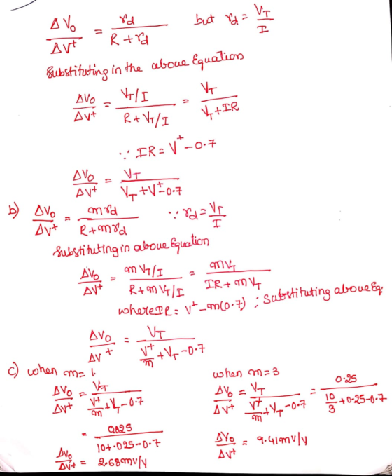
Question 2: 20% We can use stack of diodes as a voltage regulator as shown in the circuit below. Consider input voltage to this circuit as 20V DC with IV of fluctuation. Diodes in this circuit have 0.7V forward voltage drop a) What is DC output voltage Vo? 20+1V Vo= 1.4 V R=1k2 b) What is diode DC current lo? Ip= 18-6 ma c) What is the value of individual diode's small-signal resistor/? (4%)...
Please show all of the steps
Question 2: 20% We can use stack of diodes as a voltage regulator as shown in the circuit below. Consider input voltage to this circuit as 20V DC with IV of fluctuation. Diodes in this circuit have 0.7V forward voltage drop a) What is DC output voltage Vo? 20+1V Vo= 1.4 V R=1k2 b) What is diode DC current lo? Ip= 18-6 ma c) What is the value of individual diode's small-signal resistor/? (4%)...
The bridge-rectifier isce Fig. 4) circuit with a filter capacitor has R = 100 ohms. The...
 The bridge-rectifier isce Fig. 4) circuit with a filter capacitor has R = 100 ohms. The Scondary transformer delivers a sinusoid of 15 V (rrns, and has a frequency of 80 Hz. The diodes have Vo = D.7 V each. (a) What will be the value of the filter capacitor so that the Apple voltage is limited to below 100 mV peak-to-peak? (3 marks) b) What is the DC voltage at the output of the system? [2 marks) (c) What...
Q4. The diode circuit Fig. Q2a is supplied with an a.c. voltage of 100 mV. Assume...
 Q4. The diode circuit Fig. Q2a is supplied with an a.c. voltage of 100 mV. Assume that the capacitors in the circuit are short circuits at the operating frequencies. Calculate the output voltage V. (12 marks) T +10 34762 m ovo 5002 100 mVrms Q4. The diode circuit Fig. Q2a is supplied with an a.c. voltage of 100 mV. Assume that the capacitors in the circuit are short circuits at the operating frequencies. Calculate the output voltage V. (12 marks)...
Design a FULL WAVE BRIDGE RECTIFIER circuit that will: Take 120volts ac, 60 hz, sinusoidal waveform...
 Design a FULL WAVE BRIDGE RECTIFIER circuit that will:
Take 120volts ac, 60 hz, sinusoidal waveform and convert
it to a “regulated “dc value
giving 12 volts +, - 1 volt across a 2000-ohm output
load resistor with no more than 2%
ripple voltage.
You may assume:
a. An ideal power transformer as discussed in class.
b. For hand computations, you must assume a diode given by
Figure 4.8 page 185.
c. A filter capacitor sized per the textbook equation...
Design a FULL WAVE BRIDGE RECTIFIER circuit that will:
Take 120volts ac, 60 hz, sinusoidal waveform and convert
it to a “regulated “dc value
giving 12 volts +, - 1 volt across a 2000-ohm output
load resistor with no more than 2%
ripple voltage.
You may assume:
a. An ideal power transformer as discussed in class.
b. For hand computations, you must assume a diode given by
Figure 4.8 page 185.
c. A filter capacitor sized per the textbook equation...
Problem 3 (30 points): For the circuit in Fig. 3, v, has an RMS value of...
 Problem 3 (30 points): For the circuit in Fig. 3, v, has an RMS value of 9.0 V and a frequency of 60 Hz. Assume that R-20 Ω and that V,-0.7 V for each diode. Vs R o Figure 3: Circuit for Problem 3 (10 points) 1. Find the maximum value of Vo 2. Find the value of C to guarantee a ripple voltage of 0.25 V or less. (10 points) 3. For what fraction of the time is the...
Question 2 (10%) The input to the circuit shown in Fig. 2 is the voltage source...
 Question 2 (10%) The input to the circuit shown in Fig. 2 is the voltage source vs(t). The output is the voltage across two open terminals, vo(). If v()-3-(t) V, the output is the voltage vo()-10+Se30* V for 20. Determine the values of Ri and R2. 2 sa) olt) Fig. 2
Consider the circuit shown in Figure 1. Assume that the diodes have an exponen Question 21 tial i-v characteristic....
 Consider the circuit shown in Figure 1. Assume that the diodes have an exponen Question 21 tial i-v characteristic. Diode D1 has 10 times the junction area of D2, i.e. Isı = 10Is2. Determine the value of voltage V indicated in the figure. The circuit operates at room temperature, i.e. the value of the thermal voltage is Vr = 26 mV 10 mA 3 mA Fig. 1 O+V
Consider the circuit shown in Figure 1. Assume that the diodes have...
Consider the circuit shown in Figure 1. Assume that the diodes have an exponen Question 21 tial i-v characteristic. Diode D1 has 10 times the junction area of D2, i.e. Isı = 10Is2. Determine the value of voltage V indicated in the figure. The circuit operates at room temperature, i.e. the value of the thermal voltage is Vr = 26 mV 10 mA 3 mA Fig. 1 O+V
Consider the circuit shown in Figure 1. Assume that the diodes have...
4) a. In the regulator shown in figure 6, R: -60K0, R = 45KN and V2...
 4) a. In the regulator shown in figure 6, R: -60K0, R = 45KN and V2 = 5.8V. If the 12 V output drops 0.2 V, calculate the change in Vez that results. (12 Marks) Q. R V Vo Q V SR SR Figure 6 MEC_AMO_TEM_034_01 Page 5 of 10 Industrial Electronics (ELEC 20002) - Spring - 2020 - CW (Assignment 2) - ALL-QP b. Consider the voltage regulator circuit as shown in figure 7. The unregulated input voltage is...
 Part IIl: Diodes The Ideal-Diode Model a) For the circuit below, find ID and VD for the case VDD 5 V and R 10 k2. Assume that the diode has a voltage of 0.7 V at 1-mA current. Use (a) iteration and (b) the constant-voltage-drop model with VD 0.7 V 홍Yo b) Design the circuit below to provide an output voltage of 2.4 V. Assume that the diodes available have 0.7-V drop at 1 mA. +10 V Vo
Part IIl:...
Part IIl: Diodes The Ideal-Diode Model a) For the circuit below, find ID and VD for the case VDD 5 V and R 10 k2. Assume that the diode has a voltage of 0.7 V at 1-mA current. Use (a) iteration and (b) the constant-voltage-drop model with VD 0.7 V 홍Yo b) Design the circuit below to provide an output voltage of 2.4 V. Assume that the diodes available have 0.7-V drop at 1 mA. +10 V Vo
Part IIl:...
 (a) The following circuit shows a linear
voltage regulator. Assuming the zener diode has specifications (VZ
= 2.5 V, IZ = 60 mA), select adequate resistor values to provide a
regulated output voltage Vo = 10 V from an unregulated voltage Vi =
15V.
(b) Calculate the power efficiency of the
regulator when a load RL = 10Ω is connected to the regulator
output.
(c) Briefly explain the terms “dropout”, “line
regulation”, and “load regulation”, as they apply to voltage...
(a) The following circuit shows a linear
voltage regulator. Assuming the zener diode has specifications (VZ
= 2.5 V, IZ = 60 mA), select adequate resistor values to provide a
regulated output voltage Vo = 10 V from an unregulated voltage Vi =
15V.
(b) Calculate the power efficiency of the
regulator when a load RL = 10Ω is connected to the regulator
output.
(c) Briefly explain the terms “dropout”, “line
regulation”, and “load regulation”, as they apply to voltage...
 Please show all of the steps
Question 2: 20% We can use stack of diodes as a voltage regulator as shown in the circuit below. Consider input voltage to this circuit as 20V DC with IV of fluctuation. Diodes in this circuit have 0.7V forward voltage drop a) What is DC output voltage Vo? 20+1V Vo= 1.4 V R=1k2 b) What is diode DC current lo? Ip= 18-6 ma c) What is the value of individual diode's small-signal resistor/? (4%)...
Please show all of the steps
Question 2: 20% We can use stack of diodes as a voltage regulator as shown in the circuit below. Consider input voltage to this circuit as 20V DC with IV of fluctuation. Diodes in this circuit have 0.7V forward voltage drop a) What is DC output voltage Vo? 20+1V Vo= 1.4 V R=1k2 b) What is diode DC current lo? Ip= 18-6 ma c) What is the value of individual diode's small-signal resistor/? (4%)...
 The bridge-rectifier isce Fig. 4) circuit with a filter capacitor has R = 100 ohms. The Scondary transformer delivers a sinusoid of 15 V (rrns, and has a frequency of 80 Hz. The diodes have Vo = D.7 V each. (a) What will be the value of the filter capacitor so that the Apple voltage is limited to below 100 mV peak-to-peak? (3 marks) b) What is the DC voltage at the output of the system? [2 marks) (c) What...
 Q4. The diode circuit Fig. Q2a is supplied with an a.c. voltage of 100 mV. Assume that the capacitors in the circuit are short circuits at the operating frequencies. Calculate the output voltage V. (12 marks) T +10 34762 m ovo 5002 100 mVrms Q4. The diode circuit Fig. Q2a is supplied with an a.c. voltage of 100 mV. Assume that the capacitors in the circuit are short circuits at the operating frequencies. Calculate the output voltage V. (12 marks)...
 Design a FULL WAVE BRIDGE RECTIFIER circuit that will:
Take 120volts ac, 60 hz, sinusoidal waveform and convert
it to a “regulated “dc value
giving 12 volts +, - 1 volt across a 2000-ohm output
load resistor with no more than 2%
ripple voltage.
You may assume:
a. An ideal power transformer as discussed in class.
b. For hand computations, you must assume a diode given by
Figure 4.8 page 185.
c. A filter capacitor sized per the textbook equation...
Design a FULL WAVE BRIDGE RECTIFIER circuit that will:
Take 120volts ac, 60 hz, sinusoidal waveform and convert
it to a “regulated “dc value
giving 12 volts +, - 1 volt across a 2000-ohm output
load resistor with no more than 2%
ripple voltage.
You may assume:
a. An ideal power transformer as discussed in class.
b. For hand computations, you must assume a diode given by
Figure 4.8 page 185.
c. A filter capacitor sized per the textbook equation...
 Problem 3 (30 points): For the circuit in Fig. 3, v, has an RMS value of 9.0 V and a frequency of 60 Hz. Assume that R-20 Ω and that V,-0.7 V for each diode. Vs R o Figure 3: Circuit for Problem 3 (10 points) 1. Find the maximum value of Vo 2. Find the value of C to guarantee a ripple voltage of 0.25 V or less. (10 points) 3. For what fraction of the time is the...
 Question 2 (10%) The input to the circuit shown in Fig. 2 is the voltage source vs(t). The output is the voltage across two open terminals, vo(). If v()-3-(t) V, the output is the voltage vo()-10+Se30* V for 20. Determine the values of Ri and R2. 2 sa) olt) Fig. 2
 Consider the circuit shown in Figure 1. Assume that the diodes have an exponen Question 21 tial i-v characteristic. Diode D1 has 10 times the junction area of D2, i.e. Isı = 10Is2. Determine the value of voltage V indicated in the figure. The circuit operates at room temperature, i.e. the value of the thermal voltage is Vr = 26 mV 10 mA 3 mA Fig. 1 O+V
Consider the circuit shown in Figure 1. Assume that the diodes have...
Consider the circuit shown in Figure 1. Assume that the diodes have an exponen Question 21 tial i-v characteristic. Diode D1 has 10 times the junction area of D2, i.e. Isı = 10Is2. Determine the value of voltage V indicated in the figure. The circuit operates at room temperature, i.e. the value of the thermal voltage is Vr = 26 mV 10 mA 3 mA Fig. 1 O+V
Consider the circuit shown in Figure 1. Assume that the diodes have...
 4) a. In the regulator shown in figure 6, R: -60K0, R = 45KN and V2 = 5.8V. If the 12 V output drops 0.2 V, calculate the change in Vez that results. (12 Marks) Q. R V Vo Q V SR SR Figure 6 MEC_AMO_TEM_034_01 Page 5 of 10 Industrial Electronics (ELEC 20002) - Spring - 2020 - CW (Assignment 2) - ALL-QP b. Consider the voltage regulator circuit as shown in figure 7. The unregulated input voltage is...
Most questions answered within 3 hours.
-
An short-seller in Tesla is worried the latest management
earnings forecast is too aggressive and the...
asked 36 minutes ago -
Question 3 (1 point)
Fill in the blank. Speed Car Rental company found that the tire...
asked 35 minutes ago -
1. A copper wire is 26.61 cm long and weighs 1.265 g. The
density of copper...
asked 13 minutes ago -
Remember that a concept sketch consists of a sketch (or
series of sketches), labels, and complete...
asked 15 minutes ago -
on a newly discovered planet, the period of a pendulum with a
length of 2 m...
asked 17 minutes ago -
Why [M(CN)6] is not organometallic even it has metal
to carbon bond too
asked 24 minutes ago -
mstar electric has a bond issue outstanding that has a 20 year
life, a $1,000 par...
asked 31 minutes ago -
This is a Business Writing Question:
Common Types of Faulty Sentence Logic:
A. Mixed constructions
B....
asked 32 minutes ago -
Skinner asserts that science, and the common view of science, has
been tarnished. Explain his evidence...
asked 35 minutes ago -
A grocery store's receipts show that Sunday customer purchases
have a skewed distribution with a mean...
asked 41 minutes ago -
A 0.035 mol sample of a weak acid, HA, is dissolved in 437 mL of
water...
asked 53 minutes ago -
a sample of Ar gas has a volume of 6.30 L with an unknown
pressure. the...
asked 53 minutes ago