
Homework Answers
Add Answer to:
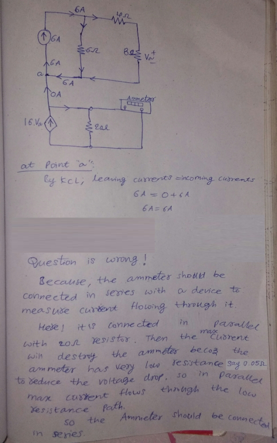
Figure P 3.6-24 P 3.6-25 Determine the current measured by the ammeter in the circuit shown...
3. The circuit is as shown below. Assuming that the ammeter and voltmeter are ideal, means...
 3. The circuit is as shown below. Assuming that the ammeter and voltmeter are ideal, means they don't affect the current in the circuit, so an ideal voltmeter has a very high resistance while an ideal ammeter has a negligible resistance. Voltmeter www 9.0 v 24 (a) What's the ammeter and voltmeter readings with the switch 's' open (0.15 A and 3.6 V (b) What's the ammeter and voltmeter readings with the switch 's' closed? (0.38 A and 9.0V) (e)...
Explain For the circuit shown in the Figure 3, R is 12.0 ? and the ammeter...
 Explain
For the circuit shown in the Figure 3, R is 12.0 ? and the ammeter reads 0.25 A 11. What is the reading of the voltmeter 12. 15.0 12, What is the voltage across the 15.0 ? resistor? Figure 3 13. If the emf of the battery is 9V, what is the internal resistance of the battery? .2S 14. Calculate the total power that dissipates in this circuit. extenal 15, which one, if either, does dissipate most power: the...
Explain
For the circuit shown in the Figure 3, R is 12.0 ? and the ammeter reads 0.25 A 11. What is the reading of the voltmeter 12. 15.0 12, What is the voltage across the 15.0 ? resistor? Figure 3 13. If the emf of the battery is 9V, what is the internal resistance of the battery? .2S 14. Calculate the total power that dissipates in this circuit. extenal 15, which one, if either, does dissipate most power: the...
P3.4-16 The input to the circuit shown in Figure P 3.4-16 is the source current is....
 P3.4-16 The input to the circuit shown in Figure P 3.4-16 is the source current is. The output is the current measured by the meter io. A current divider connects the source to the meter. Given the following observations: (a) The input is = 5 A causes the output to be i. 2 A. (b) When is = 2 A, the source supplies 48 W. Determine the values of the resistances Rį and R2. lo R2 w o Ammeter o...
Consider the circuit shown below. All three batteries are ideal. The voltmeter and ammeter are also...
 Consider the circuit shown below. All three batteries are ideal. The voltmeter and ammeter are also ideal. 7.00V 崇弓= 12.0V v) R 5.00 R2 6.00 Ω = 8.00 V A. What is the internal resistance of the batteries? B. What is the internal resistance of the voltmeter? C. what is the internal resistance of the ammeter? D. Based on your answers to questions A-C draw a simpler equivalent circuit (in the space above to the right of the original circuit)...
In the figure a voltmeter of resistance Rv = 480 s2 and an ammeter of resistance...
 In the figure a voltmeter of resistance Rv = 480 s2 and an ammeter of resistance RA = 2.03 12 are being used to measure a resistance R in a circuit that also contains Ro = 100 1 and an ideal battery of emf ε = 12.0 V. Resistance R is given by Vli, where V is the potential across R and i is the ammeter reading. The voltmeter reading is V', which is V plus the potential difference across...
Consider the circuit shown below. The 62 resistor is consuming power at a rate of 24...
 Consider the circuit shown below. The 62 resistor is consuming power at a rate of 24 J/s when the current passes through it. 20.012 1792 em الام E = ? 36.00 20.0 22 1922 25 V 33.00 130 P 1.012 (a) Find the current through the ammeter A. What are the polarity and emfe of the unknown battery? If point P of the circuit is grounded (that is Vp = 0V), what is the voltage at point Q? What is...
Question One: In the figure below, what is the reading on the ammeter in each case...
 Question One: In the figure below, what is the reading on the ammeter in each case .5 .6 (A) If you connected the circuit to the 3A setting on the ammeter, then the reading will be (B) If you connected the circuit to the 1A setting on the ammeter, then the reading will be (C) If you connected the circuit to the 300 mA setting on the ammeter, then the reading will be uestion Two: (A) Is the equivalent resistance,...
for circuit shown in figure the battery has no appreciable internal resistance. voltmeter and anmeter are...
 for circuit shown in figure the battery has no appreciable
internal resistance. voltmeter and anmeter are ideal
2. (20 points, 5 points each) For the circuit shown in Figure, the battery has no appreciable internal resistance. Voltmeter and Ammeter are ideal. (a) What is the equivalent resistance of the circuit? 3 kn 2 kn R(series Rea» 3.734 3.21: 8-73 kn (b) What does the voltmeter read? parrele witn R4 . Vz4s τ24( 2 +): o.or7 (3.73 xu?): 47. 37lV (c)...
for circuit shown in figure the battery has no appreciable
internal resistance. voltmeter and anmeter are ideal
2. (20 points, 5 points each) For the circuit shown in Figure, the battery has no appreciable internal resistance. Voltmeter and Ammeter are ideal. (a) What is the equivalent resistance of the circuit? 3 kn 2 kn R(series Rea» 3.734 3.21: 8-73 kn (b) What does the voltmeter read? parrele witn R4 . Vz4s τ24( 2 +): o.or7 (3.73 xu?): 47. 37lV (c)...
P 3.6-14 All of the resistances in the circuit shown in Figure P 3.6-14 are multiples...
 P 3.6-14 All of the resistances in the circuit shown in Figure P 3.6-14 are multiples of R. Determine the value of R. OM 2R fo.la 12v 2R 2R 3R 2R
Consider a circuit containing a 24 V battery and a 15 Ω resistor. We want to...
Consider a circuit containing a 24 V battery and a 15 Ω resistor. We want to mesure the current in the circuit with an ammeter of internal resistance 3 mΩ and the voltage drop across the resistor with a voltmeter having an internal resistance of 100 kΩ. a. How should be the ammeter connected (series or parallel)? b. How should be the voltmeter connected (series or parallel)? c. Draw a schematic of the circuit d. Calculate the current across the...
 3. The circuit is as shown below. Assuming that the ammeter and voltmeter are ideal, means they don't affect the current in the circuit, so an ideal voltmeter has a very high resistance while an ideal ammeter has a negligible resistance. Voltmeter www 9.0 v 24 (a) What's the ammeter and voltmeter readings with the switch 's' open (0.15 A and 3.6 V (b) What's the ammeter and voltmeter readings with the switch 's' closed? (0.38 A and 9.0V) (e)...
 Explain
For the circuit shown in the Figure 3, R is 12.0 ? and the ammeter reads 0.25 A 11. What is the reading of the voltmeter 12. 15.0 12, What is the voltage across the 15.0 ? resistor? Figure 3 13. If the emf of the battery is 9V, what is the internal resistance of the battery? .2S 14. Calculate the total power that dissipates in this circuit. extenal 15, which one, if either, does dissipate most power: the...
Explain
For the circuit shown in the Figure 3, R is 12.0 ? and the ammeter reads 0.25 A 11. What is the reading of the voltmeter 12. 15.0 12, What is the voltage across the 15.0 ? resistor? Figure 3 13. If the emf of the battery is 9V, what is the internal resistance of the battery? .2S 14. Calculate the total power that dissipates in this circuit. extenal 15, which one, if either, does dissipate most power: the...
 P3.4-16 The input to the circuit shown in Figure P 3.4-16 is the source current is. The output is the current measured by the meter io. A current divider connects the source to the meter. Given the following observations: (a) The input is = 5 A causes the output to be i. 2 A. (b) When is = 2 A, the source supplies 48 W. Determine the values of the resistances Rį and R2. lo R2 w o Ammeter o...
 Consider the circuit shown below. All three batteries are ideal. The voltmeter and ammeter are also ideal. 7.00V 崇弓= 12.0V v) R 5.00 R2 6.00 Ω = 8.00 V A. What is the internal resistance of the batteries? B. What is the internal resistance of the voltmeter? C. what is the internal resistance of the ammeter? D. Based on your answers to questions A-C draw a simpler equivalent circuit (in the space above to the right of the original circuit)...
 In the figure a voltmeter of resistance Rv = 480 s2 and an ammeter of resistance RA = 2.03 12 are being used to measure a resistance R in a circuit that also contains Ro = 100 1 and an ideal battery of emf ε = 12.0 V. Resistance R is given by Vli, where V is the potential across R and i is the ammeter reading. The voltmeter reading is V', which is V plus the potential difference across...
 Consider the circuit shown below. The 62 resistor is consuming power at a rate of 24 J/s when the current passes through it. 20.012 1792 em الام E = ? 36.00 20.0 22 1922 25 V 33.00 130 P 1.012 (a) Find the current through the ammeter A. What are the polarity and emfe of the unknown battery? If point P of the circuit is grounded (that is Vp = 0V), what is the voltage at point Q? What is...
 Question One: In the figure below, what is the reading on the ammeter in each case .5 .6 (A) If you connected the circuit to the 3A setting on the ammeter, then the reading will be (B) If you connected the circuit to the 1A setting on the ammeter, then the reading will be (C) If you connected the circuit to the 300 mA setting on the ammeter, then the reading will be uestion Two: (A) Is the equivalent resistance,...
 for circuit shown in figure the battery has no appreciable
internal resistance. voltmeter and anmeter are ideal
2. (20 points, 5 points each) For the circuit shown in Figure, the battery has no appreciable internal resistance. Voltmeter and Ammeter are ideal. (a) What is the equivalent resistance of the circuit? 3 kn 2 kn R(series Rea» 3.734 3.21: 8-73 kn (b) What does the voltmeter read? parrele witn R4 . Vz4s τ24( 2 +): o.or7 (3.73 xu?): 47. 37lV (c)...
for circuit shown in figure the battery has no appreciable
internal resistance. voltmeter and anmeter are ideal
2. (20 points, 5 points each) For the circuit shown in Figure, the battery has no appreciable internal resistance. Voltmeter and Ammeter are ideal. (a) What is the equivalent resistance of the circuit? 3 kn 2 kn R(series Rea» 3.734 3.21: 8-73 kn (b) What does the voltmeter read? parrele witn R4 . Vz4s τ24( 2 +): o.or7 (3.73 xu?): 47. 37lV (c)...
 P 3.6-14 All of the resistances in the circuit shown in Figure P 3.6-14 are multiples of R. Determine the value of R. OM 2R fo.la 12v 2R 2R 3R 2R
Most questions answered within 3 hours.
-
Using MARS simulator, write MIPS programs according to
the following scenarios: Receive a positive integer number...
asked 45 minutes ago -
An object in front of a concave mirror has a real image that is
11.5 cm...
asked 59 minutes ago -
Consider the reaction, C3 H8 + O2 --> CO2 + H2O. How many
moles of O2...
asked 2 hours ago -
You and your opponent both roll a fair die. If you both roll the
same number,...
asked 3 hours ago -
In a study of the accuracy of fast food drive-through orders,
Restaurant A had 257 accurate...
asked 3 hours ago -
Identify and describe in detail the four categories of
institutions that could be included in a...
asked 3 hours ago -
In python
class Customer:
def __init__(self, customer_id, last_name, first_name, phone_number, address):
self._customer_id = int(customer_id)
self._last_name =...
asked 3 hours ago -
What is an example of a limitation in implementing a new
ERP system and how it...
asked 3 hours ago -
In a section of 9.7cm of an artery with a radius of 2.6mm there
is a...
asked 3 hours ago -
the two carboxylic acid groups of aspartic acid have different
acidities with pKa values of 2.1...
asked 3 hours ago -
Would CuCO3 aqueous salt combined with calcium chloride
form a solid precipitate? If so, what would...
asked 3 hours ago -
How do ECM Solutions assist in embedding a culture of continuous
improvement in an organization? (Project...
asked 3 hours ago