
Homework Answers

Add Answer to:
The double-slider linkage is driven by moving sliding block 2 as shown in the figure. The...
Problem #7: For the linkage in Figure below, calculate and plot the angular displacement of link...
 Problem #7: For the linkage in Figure below, calculate and plot the angular displacement of link 3 and 4 and the path coordinates of Point P with respect to the input crank O2A for one revolution L-2.06 -31 AP 3.06 L4 2.33 L2 1.0 wwL2.22 02 May you please write in clear steps. Thanks
Problem #7: For the linkage in Figure below, calculate and plot the angular displacement of link 3 and 4 and the path coordinates of Point P...
Problem #7: For the linkage in Figure below, calculate and plot the angular displacement of link 3 and 4 and the path coordinates of Point P with respect to the input crank O2A for one revolution L-2.06 -31 AP 3.06 L4 2.33 L2 1.0 wwL2.22 02 May you please write in clear steps. Thanks
Problem #7: For the linkage in Figure below, calculate and plot the angular displacement of link 3 and 4 and the path coordinates of Point P...
May you please write in clear steps. Thanks Problem 5. Referring to the linkage configuration and terminology shown in...
 May you please write in clear steps. Thanks
Problem 5. Referring to the linkage configuration and terminology shown in the Figure below, draw the linkage to scale and graphically find all possible solutions for 03 and 04 for the values in a and b. Determine the Grashof condition 62 Link 4 Link 3 Link 2 Link 30 9 2 50 10 10 10 20 Open Y y A 031 BAL 2 02 Crossed Problem #6: Repeat Problem #5 but now...
May you please write in clear steps. Thanks
Problem 5. Referring to the linkage configuration and terminology shown in the Figure below, draw the linkage to scale and graphically find all possible solutions for 03 and 04 for the values in a and b. Determine the Grashof condition 62 Link 4 Link 3 Link 2 Link 30 9 2 50 10 10 10 20 Open Y y A 031 BAL 2 02 Crossed Problem #6: Repeat Problem #5 but now...
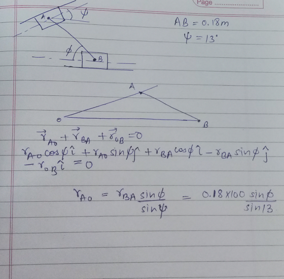
An internal combustion engine slider-crank mechanism is shown in the figure. Crank AB rotates in selected...
 An internal combustion engine slider-crank mechanism is shown in the figure. Crank AB rotates in selected clockwise positive direction as shown. Piston position is Y=AD. e(t) is angular position of the crank, ó(t) is angular velocity of the crank, ő is angular acceleration of the crank, 4) Crank AB rotates starting from rest with a constant angular acceleration of 0.25 rad/sec? ( = 0.25 rad/sec² ) clockwise in positive 0 direction as shown Perform computer simulations using above formulas to...
 Problem #7: For the linkage in Figure below, calculate and plot the angular displacement of link 3 and 4 and the path coordinates of Point P with respect to the input crank O2A for one revolution L-2.06 -31 AP 3.06 L4 2.33 L2 1.0 wwL2.22 02 May you please write in clear steps. Thanks
Problem #7: For the linkage in Figure below, calculate and plot the angular displacement of link 3 and 4 and the path coordinates of Point P...
Problem #7: For the linkage in Figure below, calculate and plot the angular displacement of link 3 and 4 and the path coordinates of Point P with respect to the input crank O2A for one revolution L-2.06 -31 AP 3.06 L4 2.33 L2 1.0 wwL2.22 02 May you please write in clear steps. Thanks
Problem #7: For the linkage in Figure below, calculate and plot the angular displacement of link 3 and 4 and the path coordinates of Point P...
 May you please write in clear steps. Thanks
Problem 5. Referring to the linkage configuration and terminology shown in the Figure below, draw the linkage to scale and graphically find all possible solutions for 03 and 04 for the values in a and b. Determine the Grashof condition 62 Link 4 Link 3 Link 2 Link 30 9 2 50 10 10 10 20 Open Y y A 031 BAL 2 02 Crossed Problem #6: Repeat Problem #5 but now...
May you please write in clear steps. Thanks
Problem 5. Referring to the linkage configuration and terminology shown in the Figure below, draw the linkage to scale and graphically find all possible solutions for 03 and 04 for the values in a and b. Determine the Grashof condition 62 Link 4 Link 3 Link 2 Link 30 9 2 50 10 10 10 20 Open Y y A 031 BAL 2 02 Crossed Problem #6: Repeat Problem #5 but now...
 An internal combustion engine slider-crank mechanism is shown in the figure. Crank AB rotates in selected clockwise positive direction as shown. Piston position is Y=AD. e(t) is angular position of the crank, ó(t) is angular velocity of the crank, ő is angular acceleration of the crank, 4) Crank AB rotates starting from rest with a constant angular acceleration of 0.25 rad/sec? ( = 0.25 rad/sec² ) clockwise in positive 0 direction as shown Perform computer simulations using above formulas to...
Most questions answered within 3 hours.
-
Calculate the equillibrium constent K for a redox reaction that
has E°cell = -.98 V at...
asked 7 minutes ago -
A concave spherical mirror has a radius of curvature of
magnitude 19.6 cm.
(a) Find the...
asked 9 minutes ago -
3. draw a diagram of the magnetic field:
a. around a long straight wire with a...
asked 7 minutes ago -
If you titrated 30.0 mL of 0.1 M HCl with 0.1 M NaOH, indicate
the approximate...
asked 16 minutes ago -
NADH passes electrons into the electron transport chain. List
the carriers that would receive the electrons,...
asked 24 minutes ago -
A cylindrical cable with a resistivity of 1.6x10⁻⁸ Ω·m and cross
sectional area of 3x10⁻⁵ m^2...
asked 24 minutes ago -
True or False.
A consumer with convex preferences who is indifferent between
the bundles (5,2) and...
asked 28 minutes ago -
A diamond's index of refraction for red light, 656 nm, is 2.410,
while that for blue...
asked 41 minutes ago -
Compare HPLC, SPE, and GC. Identify the differences, the
advantages, and the weaknesses of each method.
asked 42 minutes ago -
Characteristic x-rays emitted by potassium have a wavelength of
0.374 nm. What is the energy of...
asked 44 minutes ago -
there is a function to create two random numbers between 1 and
25 and a function...
asked 1 hour ago -
At a certain temperature, the ?pKp for the decomposition of
H2SH2S is 0.832.0.832.
H2S(g)↽−−⇀H2(g)+S(g)H2S(g)↽−−⇀H2(g)+S(g)
Initially, only...
asked 56 minutes ago