
Homework Answers

Add Answer to:
A force transduce r is a mass-spring-damper system. When an external force is applied to the...
Question8 n the spring-mass-damper system in Figure 8, the force F, is applied to the mass and it...
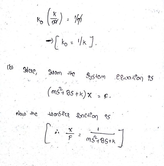
 Question8 n the spring-mass-damper system in Figure 8, the force F, is applied to the mass and its displacement is measured via r(t), whilst k and c are the spring and damper constants, respectively x(t) Figure 8: A spring-mass-damper system. a) Obtain the differential equation that relates the input force F, to the measured dis- (6 marks) placement x(t) for the system in Figure 8. b) Draw the block diagram representation of the system in Figure 8. c) Based on...
Problem 2 - A modified mass-spring-damper system: Model the modified mass-spring-damper system shown below. The mass...
 Problem 2 - A modified mass-spring-damper system: Model the modified mass-spring-damper system shown below. The mass of the handle is negligi- ble (only 1 FBD is necessary). Consider the displacement (t) to be the input to the system and the cart displacement az(t) to be the output. You may assume negligible drag. MwSpring-Damper System M0 Problem 3 Repeat problem 2, but with the following differences: • Assume the mass of the handle m, is not equal to zero. You may...
A mass-spring-damper system is shown below. If a periodic external forceAssume: r acts on the mass...
 A mass-spring-damper system is shown below. If a periodic external forceAssume: r acts on the mass as graphed below, what is the steady state response of the system? D= Spring Mass m External force r(t) Dashpot Vibrating system under considerati r(t) ?/2
Problem 1. Consider the following mass, spring, and damper system. Let the force F be the...
 Problem 1. Consider the following mass, spring, and damper system. Let the force F be the input and the position x be the output. M-1 kg b- 10 N s/m k 20 N/nm F = 1 N when t>=0 PART UNIT FEEDBACK CONTROL SYSTEM 5) Construct a unit feedback control for the mass-spring-damper system 6) Draw the block diagram of the unit feedback control system 7) Find the Transfer Function of the closed-loop (CL) system 8) Find and plot the...
Consider the mass-spring-damper system depicted in the figure below, where the input of the system is...
 Consider the mass-spring-damper system depicted in the figure below, where the input of the system is the applied force F(t) and the output of the system is xít) that is the displacement of the mass according to the coordinate system defined in that figure. Assume that force F(t) is applied for t> 0 and the system is in static equilibrium before t=0 and z(t) is measured from the static equilibrium. b m F Also, the mass of the block, the...
Problem 1 (Harmonic Oscillators) A mass-damper-spring system is a simple harmonic oscillator whose dynamics is governed...
 Problem 1 (Harmonic Oscillators) A mass-damper-spring system is a simple harmonic oscillator whose dynamics is governed by the equation of motion where m is the mass, c is the damping coefficient of the damper, k is the stiffness of the spring, F is the net force applied on the mass, and x is the displacement of the mass from its equilibrium point. In this problem, we focus on a mass-damper-spring system with m = 1 kg, c-4 kg/s, k-3 N/m,...
The equations of motion for a mass-spring-damper system can be described by mE(t) + ci(t) +...
 The equations of motion for a mass-spring-damper system can be described by mE(t) + ci(t) + k2(t) = F(t), where z(t) is the position of the mass, c is the damper coefficient, k is the spring constant, and F(t) is an external force applied to the mass as an input. If the system state vector is defined by 2(t) = lat) a(t)=F(t), y(t)=2(t), given below: x=Ax + Bu y=Cx + Du.
A second order mechanical system of a mass connected to a spring and a damper is subjected to a s...
 A second order mechanical system of a mass connected to a spring and a damper is subjected to a sinusoidal input force mi+ci +kx- Asin(ot) The mass is m-5 kg, the damping constant is c = 1 N-sec/m, the spring stiffness is 2 N/m, and the amplitude of the input force is A- 3 N. For this system give explicit numerical values for the damping factor un-damped natural frequency on a. and the
A second order mechanical system of a...
A second order mechanical system of a mass connected to a spring and a damper is subjected to a sinusoidal input force mi+ci +kx- Asin(ot) The mass is m-5 kg, the damping constant is c = 1 N-sec/m, the spring stiffness is 2 N/m, and the amplitude of the input force is A- 3 N. For this system give explicit numerical values for the damping factor un-damped natural frequency on a. and the
A second order mechanical system of a...
63 Figure P6.3 shows a mass-damper system (no stiffness, Problem 2.3). Displacement x is measured...
 63 Figure P6.3 shows a mass-damper system (no stiffness, Problem 2.3). Displacement x is measured from an equilibrium position where the damper is at the "neutral" position. The external force () is a short-duration pulse function: f(!)-5N for 0SS002 s, and f,() = 0 for t > 0.02 s. The system parameters are mass m-0.5kg and viscous friction coefficient b 3 N-s/m and the system is initially at rest. Usc Simulink to determine the system response and plot displacement xit)...
A spring mass damper system is fixed at one end. The damper behaves such that a...
A spring mass damper system is fixed at one end. The damper behaves such that a constant force of 66 N applied to the damper gives a velocity of 7.95 m/second. Determine the damping constant 'c' ?
 Question8 n the spring-mass-damper system in Figure 8, the force F, is applied to the mass and its displacement is measured via r(t), whilst k and c are the spring and damper constants, respectively x(t) Figure 8: A spring-mass-damper system. a) Obtain the differential equation that relates the input force F, to the measured dis- (6 marks) placement x(t) for the system in Figure 8. b) Draw the block diagram representation of the system in Figure 8. c) Based on...
 Problem 2 - A modified mass-spring-damper system: Model the modified mass-spring-damper system shown below. The mass of the handle is negligi- ble (only 1 FBD is necessary). Consider the displacement (t) to be the input to the system and the cart displacement az(t) to be the output. You may assume negligible drag. MwSpring-Damper System M0 Problem 3 Repeat problem 2, but with the following differences: • Assume the mass of the handle m, is not equal to zero. You may...
 A mass-spring-damper system is shown below. If a periodic external forceAssume: r acts on the mass as graphed below, what is the steady state response of the system? D= Spring Mass m External force r(t) Dashpot Vibrating system under considerati r(t) ?/2
 Problem 1. Consider the following mass, spring, and damper system. Let the force F be the input and the position x be the output. M-1 kg b- 10 N s/m k 20 N/nm F = 1 N when t>=0 PART UNIT FEEDBACK CONTROL SYSTEM 5) Construct a unit feedback control for the mass-spring-damper system 6) Draw the block diagram of the unit feedback control system 7) Find the Transfer Function of the closed-loop (CL) system 8) Find and plot the...
 Consider the mass-spring-damper system depicted in the figure below, where the input of the system is the applied force F(t) and the output of the system is xít) that is the displacement of the mass according to the coordinate system defined in that figure. Assume that force F(t) is applied for t> 0 and the system is in static equilibrium before t=0 and z(t) is measured from the static equilibrium. b m F Also, the mass of the block, the...
 Problem 1 (Harmonic Oscillators) A mass-damper-spring system is a simple harmonic oscillator whose dynamics is governed by the equation of motion where m is the mass, c is the damping coefficient of the damper, k is the stiffness of the spring, F is the net force applied on the mass, and x is the displacement of the mass from its equilibrium point. In this problem, we focus on a mass-damper-spring system with m = 1 kg, c-4 kg/s, k-3 N/m,...
 The equations of motion for a mass-spring-damper system can be described by mE(t) + ci(t) + k2(t) = F(t), where z(t) is the position of the mass, c is the damper coefficient, k is the spring constant, and F(t) is an external force applied to the mass as an input. If the system state vector is defined by 2(t) = lat) a(t)=F(t), y(t)=2(t), given below: x=Ax + Bu y=Cx + Du.
 A second order mechanical system of a mass connected to a spring and a damper is subjected to a sinusoidal input force mi+ci +kx- Asin(ot) The mass is m-5 kg, the damping constant is c = 1 N-sec/m, the spring stiffness is 2 N/m, and the amplitude of the input force is A- 3 N. For this system give explicit numerical values for the damping factor un-damped natural frequency on a. and the
A second order mechanical system of a...
A second order mechanical system of a mass connected to a spring and a damper is subjected to a sinusoidal input force mi+ci +kx- Asin(ot) The mass is m-5 kg, the damping constant is c = 1 N-sec/m, the spring stiffness is 2 N/m, and the amplitude of the input force is A- 3 N. For this system give explicit numerical values for the damping factor un-damped natural frequency on a. and the
A second order mechanical system of a...
 63 Figure P6.3 shows a mass-damper system (no stiffness, Problem 2.3). Displacement x is measured from an equilibrium position where the damper is at the "neutral" position. The external force () is a short-duration pulse function: f(!)-5N for 0SS002 s, and f,() = 0 for t > 0.02 s. The system parameters are mass m-0.5kg and viscous friction coefficient b 3 N-s/m and the system is initially at rest. Usc Simulink to determine the system response and plot displacement xit)...
Most questions answered within 3 hours.
-
Seasonal or cyclical variation in a time-series model…
---exhibits irregular
variation that can be accounted for...
asked 56 seconds from now -
Please use Barney's VRIO framework of analysis to evaluate a
firm's competencies. Please choose a specific...
asked 11 minutes ago -
Where would you expect to have diabetes contributing to the most
DALYs in 2035, according to...
asked 13 minutes ago -
1.) Major league baseball salaries averaged $1.5 million with a
standard deviation of $1 million in...
asked 22 minutes ago -
A hedge fund is holding a three-year,
$10 million face value 6 percent annual coupon bond...
asked 33 minutes ago -
The focal length of a makeup (concave) mirror is 0.48 m. What
magnification does this mirror...
asked 37 minutes ago -
TRUE/FALSE
Long-lived assets that are tangible in nature, used in the
operations of the business, and...
asked 38 minutes ago -
A dragon biologist is setting up an experimental population of
1000 individuals. In dragons, pointy crests...
asked 49 minutes ago -
A uniform thin rod of length 0.851 m is hung from a horizontal
nail passing through...
asked 59 minutes ago -
A 747 has a cruising speed of 235 m/s at a height of 10,700
meters. The...
asked 1 hour ago -
Part 3: Arrows
Write a python program that prompts the user for a number of
columns,...
asked 1 hour ago -
Need help answering these questions!!
1. What economic concept do you find most interesting in
Macroeconomics?...
asked 1 hour ago