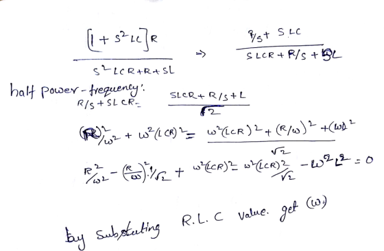
. For the following filter, a. What is the filter type? b. Find
the filter transfer function (in s-domain), c. Find its center
frequency, half-power frequency, bandwidth, and quality
factor.
Homework Answers

Add Answer to:
. For the following filter, a. What is the filter type? b. Find
the filter transfer...
For the Multi Feedback Topology Band-pass Filter circuit shown in Figure 1 below, confirm the transfer...
 For the Multi Feedback Topology Band-pass Filter circuit shown in Figure 1 below, confirm the transfer function H(s) given below 0 Figure 1: Multiple Feedback Topology Band-pass Filter (MFT BPF) Vo SR で 1 Ri R3 2R TR2C where the filter's parameters are o f: middle (center) frequency in Hz o Am: gain at middle frequency, fm, in V/V o B: bandwidth between half power frequencies in Hz o Q: quality factor. One of the nice features of this circuit...
Consider the following transfer function of a bandpass filter: 20 1,500 T(S) = 2 1,500 +...
 Consider the following transfer function of a bandpass filter: 20 1,500 T(S) = 2 1,500 + 1)(30.000 +1) a) Draw the Bode plot (magnitude and phase) of T(s). Label the slopes (dB/decade) b) Name the filter type. c) Determine the resonant frequency o d) Determine the gain in dB at the resonant frequency e) Determine bandwidth B, and the quality factor of the filter. Magnitude (dB) Phase (Deg)
1. Design a parallel RLC bandpass filter, derive the transfer function H(s). Compute the center frequency, Wo. Calculate the cutoff frequencies Wej and Wc2, the bandwidth ß, and quality factor, Q. Co...
 1. Design a parallel RLC bandpass filter, derive the transfer function H(s). Compute the center frequency, Wo. Calculate the cutoff frequencies Wej and Wc2, the bandwidth ß, and quality factor, Q. Compute values for R and L to yield a bandpass filter with a center frequency of 5kHz and a bandwidth of 200Hz, using a 10nF capacitor. (25 points)
1. Design a parallel RLC bandpass filter, derive the transfer function H(s). Compute the center frequency, Wo. Calculate the cutoff frequencies...
1. Design a parallel RLC bandpass filter, derive the transfer function H(s). Compute the center frequency, Wo. Calculate the cutoff frequencies Wej and Wc2, the bandwidth ß, and quality factor, Q. Compute values for R and L to yield a bandpass filter with a center frequency of 5kHz and a bandwidth of 200Hz, using a 10nF capacitor. (25 points)
1. Design a parallel RLC bandpass filter, derive the transfer function H(s). Compute the center frequency, Wo. Calculate the cutoff frequencies...
Problem 3. Show that the circuit shown below behaves as a bandpass filter. (Hint-find the transfer...
 Problem 3. Show that the circuit shown below behaves as a bandpass filter. (Hint-find the transfer function for this circuit and show that it has the same form as the transfer function for a bandpass filter. a) Find he center frequency, bandwidth and gain for this bandpass filter. b) Find the cutoff frequencies and the quality for this bandpass filter 10 AF HA 400 SOLF
Consider the following circuit shown in Figure P4.
 Consider the following circuit shown in Figure P4. a. Calculate the transfer function H(s) = b. Show that the circuit is a bandreject filter. c. Find the bandwidth, center frequency, the cutoff frequencies and the quality factor of the filter?
Consider the filter shown in Figure P1 a) Show that the circuit behaves as a band-pass...
 Consider the filter shown in Figure P1 a) Show that the circuit behaves as a band-pass fiter. (Hint: Find the transfer for this circuit and show that it has the same form as the transfer function for a band-pass filter.) b) Find the center frequency, bandwidth and gain for this band-pass filter c) Find the cutoff frequencies and the quality factor for this band-pass filter. 10 u.F 5 k2 50mF 16 400 (2 Figure P1
Problem 2 Consider the following circuit 4 HF o(t) 6 Q 10 mH 60 vi(t) Figure 2 1. Determine the filter type and specify...
 Problem 2 Consider the following circuit 4 HF o(t) 6 Q 10 mH 60 vi(t) Figure 2 1. Determine the filter type and specify its parameters (e.g., center frequency and bandwidth) W +
Problem 2 Consider the following circuit 4 HF o(t) 6 Q 10 mH 60 vi(t) Figure 2 1. Determine the filter type and specify its parameters (e.g., center frequency and bandwidth) W +
Problem 2 Consider the following circuit 4 HF o(t) 6 Q 10 mH 60 vi(t) Figure 2 1. Determine the filter type and specify its parameters (e.g., center frequency and bandwidth) W +
1. Design the following series RLC filter (find values of R and L) with a quality...
 1. Design the following series RLC filter (find values of R and L) with a quality factor of 5 and a center frequency of 20 krad / s. For the filter that you designed, find the bandwidth and the values of two cutoff frequencies 0.05 HF L
Problem 4 Use a 5 nF capacitor to design a series RLC bandpass filter. The center...
 Problem 4 Use a 5 nF capacitor to design a series RLC bandpass filter. The center frequency the filter is 8 kHz, and the quality factor is 1.5. Part A Specify the value of L. View Available Hint(s) EVO AQH vec ? L = 0.079 ml Submit Previous Answers * Incorrect; Try Again; 8 attempts remaining Part B Specify the value of R. 10 AEDIf vec ? R = k12 Submit Request Answer Problem 4 Use a 5 nF capacitor...
51 For the low pass filter in figure 5 find: [2 Marks] Cutoff(Critical) frequency Output Voltage...
 51 For the low pass filter in figure 5 find: [2 Marks] Cutoff(Critical) frequency Output Voltage at Cut off frequency 4.7 k C 1020 V 10 F Figure 5 6 Find at resonance from figure 5: [3 Marks] a. Resonant Frequency. d. Quality factor. e. Bandwidth b. Impedance at resonance f. Current at the half power Current at resonance. c. Vs 10 v L-1mH C-10uF R-102 C L R V Figure 5
 For the Multi Feedback Topology Band-pass Filter circuit shown in Figure 1 below, confirm the transfer function H(s) given below 0 Figure 1: Multiple Feedback Topology Band-pass Filter (MFT BPF) Vo SR で 1 Ri R3 2R TR2C where the filter's parameters are o f: middle (center) frequency in Hz o Am: gain at middle frequency, fm, in V/V o B: bandwidth between half power frequencies in Hz o Q: quality factor. One of the nice features of this circuit...
 Consider the following transfer function of a bandpass filter: 20 1,500 T(S) = 2 1,500 + 1)(30.000 +1) a) Draw the Bode plot (magnitude and phase) of T(s). Label the slopes (dB/decade) b) Name the filter type. c) Determine the resonant frequency o d) Determine the gain in dB at the resonant frequency e) Determine bandwidth B, and the quality factor of the filter. Magnitude (dB) Phase (Deg)
 1. Design a parallel RLC bandpass filter, derive the transfer function H(s). Compute the center frequency, Wo. Calculate the cutoff frequencies Wej and Wc2, the bandwidth ß, and quality factor, Q. Compute values for R and L to yield a bandpass filter with a center frequency of 5kHz and a bandwidth of 200Hz, using a 10nF capacitor. (25 points)
1. Design a parallel RLC bandpass filter, derive the transfer function H(s). Compute the center frequency, Wo. Calculate the cutoff frequencies...
1. Design a parallel RLC bandpass filter, derive the transfer function H(s). Compute the center frequency, Wo. Calculate the cutoff frequencies Wej and Wc2, the bandwidth ß, and quality factor, Q. Compute values for R and L to yield a bandpass filter with a center frequency of 5kHz and a bandwidth of 200Hz, using a 10nF capacitor. (25 points)
1. Design a parallel RLC bandpass filter, derive the transfer function H(s). Compute the center frequency, Wo. Calculate the cutoff frequencies...
 Problem 3. Show that the circuit shown below behaves as a bandpass filter. (Hint-find the transfer function for this circuit and show that it has the same form as the transfer function for a bandpass filter. a) Find he center frequency, bandwidth and gain for this bandpass filter. b) Find the cutoff frequencies and the quality for this bandpass filter 10 AF HA 400 SOLF
 Consider the filter shown in Figure P1 a) Show that the circuit behaves as a band-pass fiter. (Hint: Find the transfer for this circuit and show that it has the same form as the transfer function for a band-pass filter.) b) Find the center frequency, bandwidth and gain for this band-pass filter c) Find the cutoff frequencies and the quality factor for this band-pass filter. 10 u.F 5 k2 50mF 16 400 (2 Figure P1
 Problem 2 Consider the following circuit 4 HF o(t) 6 Q 10 mH 60 vi(t) Figure 2 1. Determine the filter type and specify its parameters (e.g., center frequency and bandwidth) W +
Problem 2 Consider the following circuit 4 HF o(t) 6 Q 10 mH 60 vi(t) Figure 2 1. Determine the filter type and specify its parameters (e.g., center frequency and bandwidth) W +
Problem 2 Consider the following circuit 4 HF o(t) 6 Q 10 mH 60 vi(t) Figure 2 1. Determine the filter type and specify its parameters (e.g., center frequency and bandwidth) W +
 1. Design the following series RLC filter (find values of R and L) with a quality factor of 5 and a center frequency of 20 krad / s. For the filter that you designed, find the bandwidth and the values of two cutoff frequencies 0.05 HF L
 Problem 4 Use a 5 nF capacitor to design a series RLC bandpass filter. The center frequency the filter is 8 kHz, and the quality factor is 1.5. Part A Specify the value of L. View Available Hint(s) EVO AQH vec ? L = 0.079 ml Submit Previous Answers * Incorrect; Try Again; 8 attempts remaining Part B Specify the value of R. 10 AEDIf vec ? R = k12 Submit Request Answer Problem 4 Use a 5 nF capacitor...
 51 For the low pass filter in figure 5 find: [2 Marks] Cutoff(Critical) frequency Output Voltage at Cut off frequency 4.7 k C 1020 V 10 F Figure 5 6 Find at resonance from figure 5: [3 Marks] a. Resonant Frequency. d. Quality factor. e. Bandwidth b. Impedance at resonance f. Current at the half power Current at resonance. c. Vs 10 v L-1mH C-10uF R-102 C L R V Figure 5
Most questions answered within 3 hours.
-
Write a program to score the paper-rock-scissor game. Each of
two users types in either P,R...
asked 13 minutes ago -
Calculate the equillibrium constent K for a redox reaction that
has E°cell = -.98 V at...
asked 25 minutes ago -
A concave spherical mirror has a radius of curvature of
magnitude 19.6 cm.
(a) Find the...
asked 27 minutes ago -
3. draw a diagram of the magnetic field:
a. around a long straight wire with a...
asked 26 minutes ago -
If you titrated 30.0 mL of 0.1 M HCl with 0.1 M NaOH, indicate
the approximate...
asked 34 minutes ago -
NADH passes electrons into the electron transport chain. List
the carriers that would receive the electrons,...
asked 42 minutes ago -
A cylindrical cable with a resistivity of 1.6x10⁻⁸ Ω·m and cross
sectional area of 3x10⁻⁵ m^2...
asked 42 minutes ago -
True or False.
A consumer with convex preferences who is indifferent between
the bundles (5,2) and...
asked 46 minutes ago -
A diamond's index of refraction for red light, 656 nm, is 2.410,
while that for blue...
asked 59 minutes ago -
Compare HPLC, SPE, and GC. Identify the differences, the
advantages, and the weaknesses of each method.
asked 1 hour ago -
Characteristic x-rays emitted by potassium have a wavelength of
0.374 nm. What is the energy of...
asked 1 hour ago -
there is a function to create two random numbers between 1 and
25 and a function...
asked 1 hour ago