a. For the circuit given in Figure 6
i. Find the load resistance RL that will receive maximum power and determine the maximum power.
ii. Determine the power dissipated on the load when RL = 2 Ω and RL = 10 Ω.
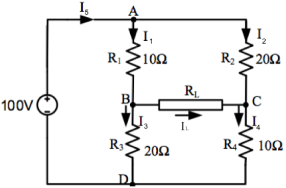
Figure 6
b. For the circuit shown in Figure 4, determine:
iii. The power delivered to the load.
iv. The impedance required in a matching network that will receive maximum power.
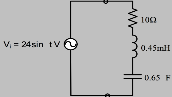
Figure 4
Homework Answers
Request Answer!
We need at least 10 more requests to produce the answer.
0 / 10 have requested this problem solution
The more requests, the faster the answer.
Add Answer to:
a. For the circuit given in Figure 6
i. Find the load resistance RL that will...
For the circuit, determine A. the value for the load resistance, RL, so that maximum power...
 For the circuit, determine
A. the value for the load resistance, RL, so that maximum power is
delivered to the load
B. the maximum power that can be delivered to the load.
5.ค. ba 1n 2A
For the circuit, determine
A. the value for the load resistance, RL, so that maximum power is
delivered to the load
B. the maximum power that can be delivered to the load.
5.ค. ba 1n 2A
Given: The circuit shown above. Required: Calculate the value of the load resistor, RL, that will...
 Given: The circuit shown above.
Required: Calculate the value of the load resistor,
RL, that will draw the maximum power from the circuit.
Also, calculate the maximum amount of power that can be delivered
to RL from the circuit.
Solution:
RL = ______ Ω
Pmx = ______ W
15 о 12 O
Given: The circuit shown above.
Required: Calculate the value of the load resistor,
RL, that will draw the maximum power from the circuit.
Also, calculate the maximum amount of power that can be delivered
to RL from the circuit.
Solution:
RL = ______ Ω
Pmx = ______ W
15 о 12 O
Use Thevenin analysis with R1=10Ω, R2=20Ω, and R3= 23 Ω to determine the load RL resulting...
 Use Thevenin analysis with R1=10Ω, R2=20Ω, and R3= 23 Ω to
determine the load RL resulting in maximum power transfer and the
power delivered to the load,
a) What load resistor
RL connected to terminals ab will result in maximum power
transfer?
Select one:
a. 53.000
b. 13.019
c. 6.970
d. 10.698
b) what is the maximum power delivered to RL?
o a ЗА o b
Use Thevenin analysis with R1=10Ω, R2=20Ω, and R3= 23 Ω to
determine the load RL resulting in maximum power transfer and the
power delivered to the load,
a) What load resistor
RL connected to terminals ab will result in maximum power
transfer?
Select one:
a. 53.000
b. 13.019
c. 6.970
d. 10.698
b) what is the maximum power delivered to RL?
o a ЗА o b
a) find the no-load value of v0 in the circuit shown b) find v0 when RL...
 a) find the no-load value of v0 in the circuit shown
b) find v0 when RL is 150 k(ohms)
c) how much power is dissipated in the 25 k(ohms) resistor if the
load terminals are accidentally short-circuited?
d) what is the maximum power dissipated in thr 75 k(ohms) resistor
when RL is 150 k(ohms)?
a) Find the no-load value of vo in the circuit shown. b) Find vo when Rt is 150 kQ. c) How much power is dissipated in...
a) find the no-load value of v0 in the circuit shown
b) find v0 when RL is 150 k(ohms)
c) how much power is dissipated in the 25 k(ohms) resistor if the
load terminals are accidentally short-circuited?
d) what is the maximum power dissipated in thr 75 k(ohms) resistor
when RL is 150 k(ohms)?
a) Find the no-load value of vo in the circuit shown. b) Find vo when Rt is 150 kQ. c) How much power is dissipated in...
6. (15 pts) For the following circuit, there is a variable resistor as the load resistor....
 6. (15 pts) For the following circuit, there is a variable resistor as the load resistor. Determine the value of R that results in maximum power transfer. V1 = 20 V, R1 = 10 Ω, R2 15 Ω, R3 5 Ω, what is the power that is dissipated in R at this value?
Maximum Power Transfer Learning Goal: To find the load resistance and load power for the maximum...
 Maximum Power Transfer
Learning Goal:
To find the load resistance and load power for the maximum power
transferred to a load.
A resistive network containing independent and dependent sources
can be modeled with a Thévenin equivalent circuit, as shown below.
Maximum power transfer occurs when the load resistance
RLequals the Thévenin resistance RTh
Part A
Find the Thévenin equivalent circuit with respect to the
terminals a,b for the circuit above. What is the
Thévenin voltage VTh?
Express your answer in...
Maximum Power Transfer
Learning Goal:
To find the load resistance and load power for the maximum power
transferred to a load.
A resistive network containing independent and dependent sources
can be modeled with a Thévenin equivalent circuit, as shown below.
Maximum power transfer occurs when the load resistance
RLequals the Thévenin resistance RTh
Part A
Find the Thévenin equivalent circuit with respect to the
terminals a,b for the circuit above. What is the
Thévenin voltage VTh?
Express your answer in...
For the given circuit, find the following: The total load resistance of the circuit between circuit...
 For the given circuit, find the following:
The total load resistance of the circuit between circuit points
a and b.
The current through each resistor.
The voltage across each resistor.
The power dissipated by each resistor.
The power supplied by the battery.
The terminal voltage, Vab.
Please be as detailed as possible and explain each
step.
10.0 Ω - 8.0 Ω 6.0 Ω 4.0 Ω LW 5.0 Ω a r=0.50 Ω - L (a) & = 9.0V
For the given circuit, find the following:
The total load resistance of the circuit between circuit points
a and b.
The current through each resistor.
The voltage across each resistor.
The power dissipated by each resistor.
The power supplied by the battery.
The terminal voltage, Vab.
Please be as detailed as possible and explain each
step.
10.0 Ω - 8.0 Ω 6.0 Ω 4.0 Ω LW 5.0 Ω a r=0.50 Ω - L (a) & = 9.0V
MULTISIM 10.65 The variable load resistor R¡ in the circuit shown in PSPICE Fig. P10.65 is...
 MULTISIM 10.65 The variable load resistor R¡ in the circuit shown in PSPICE Fig. P10.65 is adjusted for maximum average power transfer to RL a) Find the maximum average power. b) What percentage of the average power devel- oped by the ideal voltage source is delivered to Rź when R is absorbing maximum average power? c) Test your solution by showing that the power developed by the ideal voltage source equals the power dissipated in the circuit. Figure P10.65 1212...
1) A lossless transmission line that is 3N2 long with an impedance of 75Ω terminated by a load of...
 1) A lossless transmission line that is 3N2 long with an impedance of 75Ω terminated by a load of 25 Ω The generator has a voltage of V,r-2sin(et) V and an internal impedance Ζ'50Ω (a) For this circuit give Vg, T, and the voltage standing wave ratio. (b) Give Vin. Inand Vo (c) Give and I (d) Give the voltage and current at the midpoint of the line (ie. P(z) and I(2) at z-3/4). (e) From the answer of (d)...
Consider the circuit shown in the figure where R1 = R2 = 225 Ω , L1...
 Consider the circuit shown in the figure where
R1 = R2 = 225 Ω ,
L1 = 25 mH , L2
= 50 mH , C = 1.25
μF ,V0 = 85 V ,
and ω = 60 s−1 . (Figure 1)
1. Find the power dissipated by R1.
2. Find the power dissipated by R2.
3. At what frequency or frequencies will both resistors
dissipate the same power?
If you need to enter more than one answer, enter them in
ascending order, separated by commas....
Consider the circuit shown in the figure where
R1 = R2 = 225 Ω ,
L1 = 25 mH , L2
= 50 mH , C = 1.25
μF ,V0 = 85 V ,
and ω = 60 s−1 . (Figure 1)
1. Find the power dissipated by R1.
2. Find the power dissipated by R2.
3. At what frequency or frequencies will both resistors
dissipate the same power?
If you need to enter more than one answer, enter them in
ascending order, separated by commas....
 For the circuit, determine
A. the value for the load resistance, RL, so that maximum power is
delivered to the load
B. the maximum power that can be delivered to the load.
5.ค. ba 1n 2A
For the circuit, determine
A. the value for the load resistance, RL, so that maximum power is
delivered to the load
B. the maximum power that can be delivered to the load.
5.ค. ba 1n 2A
 Given: The circuit shown above.
Required: Calculate the value of the load resistor,
RL, that will draw the maximum power from the circuit.
Also, calculate the maximum amount of power that can be delivered
to RL from the circuit.
Solution:
RL = ______ Ω
Pmx = ______ W
15 о 12 O
Given: The circuit shown above.
Required: Calculate the value of the load resistor,
RL, that will draw the maximum power from the circuit.
Also, calculate the maximum amount of power that can be delivered
to RL from the circuit.
Solution:
RL = ______ Ω
Pmx = ______ W
15 о 12 O
 Use Thevenin analysis with R1=10Ω, R2=20Ω, and R3= 23 Ω to
determine the load RL resulting in maximum power transfer and the
power delivered to the load,
a) What load resistor
RL connected to terminals ab will result in maximum power
transfer?
Select one:
a. 53.000
b. 13.019
c. 6.970
d. 10.698
b) what is the maximum power delivered to RL?
o a ЗА o b
Use Thevenin analysis with R1=10Ω, R2=20Ω, and R3= 23 Ω to
determine the load RL resulting in maximum power transfer and the
power delivered to the load,
a) What load resistor
RL connected to terminals ab will result in maximum power
transfer?
Select one:
a. 53.000
b. 13.019
c. 6.970
d. 10.698
b) what is the maximum power delivered to RL?
o a ЗА o b
 a) find the no-load value of v0 in the circuit shown
b) find v0 when RL is 150 k(ohms)
c) how much power is dissipated in the 25 k(ohms) resistor if the
load terminals are accidentally short-circuited?
d) what is the maximum power dissipated in thr 75 k(ohms) resistor
when RL is 150 k(ohms)?
a) Find the no-load value of vo in the circuit shown. b) Find vo when Rt is 150 kQ. c) How much power is dissipated in...
a) find the no-load value of v0 in the circuit shown
b) find v0 when RL is 150 k(ohms)
c) how much power is dissipated in the 25 k(ohms) resistor if the
load terminals are accidentally short-circuited?
d) what is the maximum power dissipated in thr 75 k(ohms) resistor
when RL is 150 k(ohms)?
a) Find the no-load value of vo in the circuit shown. b) Find vo when Rt is 150 kQ. c) How much power is dissipated in...
 6. (15 pts) For the following circuit, there is a variable resistor as the load resistor. Determine the value of R that results in maximum power transfer. V1 = 20 V, R1 = 10 Ω, R2 15 Ω, R3 5 Ω, what is the power that is dissipated in R at this value?
 Maximum Power Transfer
Learning Goal:
To find the load resistance and load power for the maximum power
transferred to a load.
A resistive network containing independent and dependent sources
can be modeled with a Thévenin equivalent circuit, as shown below.
Maximum power transfer occurs when the load resistance
RLequals the Thévenin resistance RTh
Part A
Find the Thévenin equivalent circuit with respect to the
terminals a,b for the circuit above. What is the
Thévenin voltage VTh?
Express your answer in...
Maximum Power Transfer
Learning Goal:
To find the load resistance and load power for the maximum power
transferred to a load.
A resistive network containing independent and dependent sources
can be modeled with a Thévenin equivalent circuit, as shown below.
Maximum power transfer occurs when the load resistance
RLequals the Thévenin resistance RTh
Part A
Find the Thévenin equivalent circuit with respect to the
terminals a,b for the circuit above. What is the
Thévenin voltage VTh?
Express your answer in...
 For the given circuit, find the following:
The total load resistance of the circuit between circuit points
a and b.
The current through each resistor.
The voltage across each resistor.
The power dissipated by each resistor.
The power supplied by the battery.
The terminal voltage, Vab.
Please be as detailed as possible and explain each
step.
10.0 Ω - 8.0 Ω 6.0 Ω 4.0 Ω LW 5.0 Ω a r=0.50 Ω - L (a) & = 9.0V
For the given circuit, find the following:
The total load resistance of the circuit between circuit points
a and b.
The current through each resistor.
The voltage across each resistor.
The power dissipated by each resistor.
The power supplied by the battery.
The terminal voltage, Vab.
Please be as detailed as possible and explain each
step.
10.0 Ω - 8.0 Ω 6.0 Ω 4.0 Ω LW 5.0 Ω a r=0.50 Ω - L (a) & = 9.0V
 MULTISIM 10.65 The variable load resistor R¡ in the circuit shown in PSPICE Fig. P10.65 is adjusted for maximum average power transfer to RL a) Find the maximum average power. b) What percentage of the average power devel- oped by the ideal voltage source is delivered to Rź when R is absorbing maximum average power? c) Test your solution by showing that the power developed by the ideal voltage source equals the power dissipated in the circuit. Figure P10.65 1212...
 1) A lossless transmission line that is 3N2 long with an impedance of 75Ω terminated by a load of 25 Ω The generator has a voltage of V,r-2sin(et) V and an internal impedance Ζ'50Ω (a) For this circuit give Vg, T, and the voltage standing wave ratio. (b) Give Vin. Inand Vo (c) Give and I (d) Give the voltage and current at the midpoint of the line (ie. P(z) and I(2) at z-3/4). (e) From the answer of (d)...
 Consider the circuit shown in the figure where
R1 = R2 = 225 Ω ,
L1 = 25 mH , L2
= 50 mH , C = 1.25
μF ,V0 = 85 V ,
and ω = 60 s−1 . (Figure 1)
1. Find the power dissipated by R1.
2. Find the power dissipated by R2.
3. At what frequency or frequencies will both resistors
dissipate the same power?
If you need to enter more than one answer, enter them in
ascending order, separated by commas....
Consider the circuit shown in the figure where
R1 = R2 = 225 Ω ,
L1 = 25 mH , L2
= 50 mH , C = 1.25
μF ,V0 = 85 V ,
and ω = 60 s−1 . (Figure 1)
1. Find the power dissipated by R1.
2. Find the power dissipated by R2.
3. At what frequency or frequencies will both resistors
dissipate the same power?
If you need to enter more than one answer, enter them in
ascending order, separated by commas....
Most questions answered within 3 hours.
-
The majority of innovation organizational communication has
been driven by technological advancements in the past thirty...
asked 7 minutes ago -
If one motor has three times as much power as another, then the
smaller power motor:...
asked 5 minutes ago -
Assume that the mutation rate for a given gene is
510-6 mutations per gene per generation....
asked 7 minutes ago -
A survey of tobacco use in high schools tested the saliva of
female and male students...
asked 7 minutes ago -
Discuss at least four issues that are important to
accountants.
I need 2 pages of explanations
asked 6 minutes ago -
a crate of apples with a mass of 24.8 kg is on a ramp with angle...
asked 15 minutes ago -
In 2014, Damian Walters demonstrated that he could run through a
vertical loop (after a lot...
asked 15 minutes ago -
Which one is better to use to extract beta-carotene from carrot
acetone or ethanol? is there...
asked 18 minutes ago -
discuss guidelines for using punishment wisely and why using
punishment can become “habit-forming”
asked 40 minutes ago -
2 The goal of
a _______________________________________ is to estimate
the profit potential of an product at an...
asked 23 minutes ago -
Is the dissolution of the salt A(OH)2 a reaction that increases
the disorder, or decreases the...
asked 38 minutes ago -
Do a five force analysis of the personal computer industry. Why
did Apple struggle historically in...
asked 31 minutes ago