
Homework Answers

Add Answer to:
1. Consider the circuit below, with known values of R, C, and £. (a) With the...
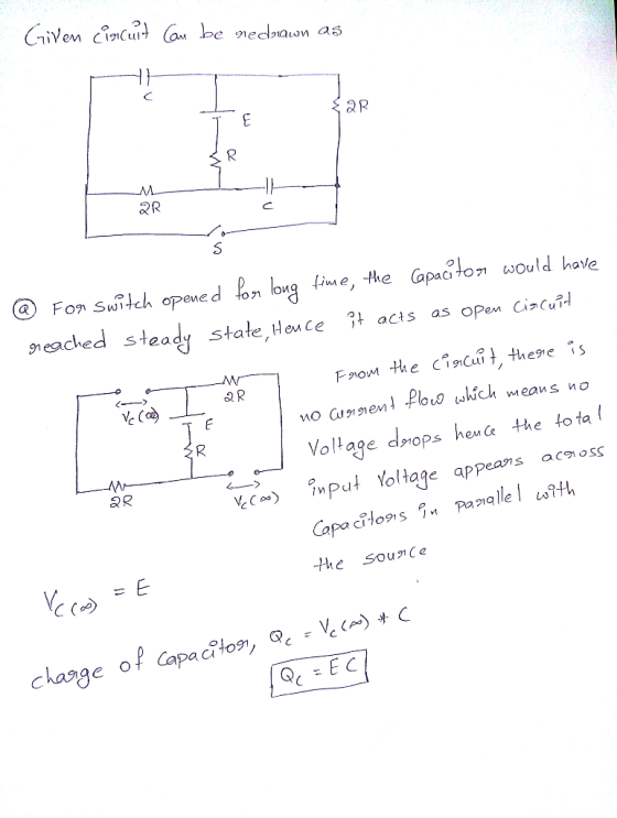
1- (25 pts) Consider the DC circuit shown in the figure. Determine the final value of...
 1- (25 pts) Consider the DC circuit shown in the figure. Determine the final value of the charges in each capacitor separately for the case when (a) the switch S is open (as in the figure) and a long time passed, and (b) the switch S is now closed and a long time has passed in this setting Note: micro means 1/1000000 and kilo means 1000; give numerical values, do not forget to include the units C2 9 V (b)...
Consider the RC circuit in the figure. The switch has been open for a long time...
 Consider the RC circuit in the figure. The switch has been open for a long time and is closed at t=0s. The capacitor initially uncharged. (a) Immediately after the switch is closed, what is value of the current through each resistor? (b) After a long time has elapsed and the capacitor is fully charged, what is the value of the current through each resistor and the charge on the capacitor?
A circuit is constructed with four resistors, one capacitor, one battery and a switch as shown....
 A circuit is constructed with four resistors, one capacitor, one
battery and a switch as shown. The values for the resistors are:
R1
= R2
= 67 ?, R3
= 96 ? and R4
= 77 ?. The capacitance is C = 48 ?F and the battery voltage is V =
24 V.
Consider the circuit above, with R5
= 67 ? in series with the capacitor. Once again, the switch has
been open for a long time when at...
A circuit is constructed with four resistors, one capacitor, one
battery and a switch as shown. The values for the resistors are:
R1
= R2
= 67 ?, R3
= 96 ? and R4
= 77 ?. The capacitance is C = 48 ?F and the battery voltage is V =
24 V.
Consider the circuit above, with R5
= 67 ? in series with the capacitor. Once again, the switch has
been open for a long time when at...
Part A Learning Goal To understand the dynamics of a series R-C circuit. Immediately after the...
 Part A Learning Goal To understand the dynamics of a series R-C circuit. Immediately after the switch is closed, what is the voltage across the capacitor? Consider a series circuit containing a resistor of resistance R and a capacitor of capacitance C connected to a source of EMF with negligible internal resistance. The wires are also assumed to have zero resistance. Initially, the switch is open and the capacitor discharged. (Figure 1) zero Let us try to understand the processes...
For the circuit shown, the switch has been open for a long time. Explain about charges,...
 For
the circuit shown, the switch has been open for a long time.
Explain about charges, currents, and voltages. Now, the switch
closed at t1. Explain what is now true about the charges, currents,
and voltages. Did the charge in C2 increase, or decrease?
For
the circuit shown, the switch has been open for a long time.
Explain about charges, currents, and voltages. Now, the switch
closed at t1. Explain what is now true about the charges, currents,
and voltages. Did the charge in C2 increase, or decrease?
A circuit is constructed with four resistors, one capacitor, one battery and a switch as shown....
 A circuit is constructed with four resistors, one capacitor, one
battery and a switch as shown. The values for the resistors are: R1
= R2 = 60 Ω, R3 = 49 Ω and R4 = 133 Ω. The capacitance is C = 75 μF
and the battery voltage is V = 24 V.
1)
The switch has been open for a long time when at time t = 0, the
switch is closed. What is I1(0), the magnitude of the...
A circuit is constructed with four resistors, one capacitor, one
battery and a switch as shown. The values for the resistors are: R1
= R2 = 60 Ω, R3 = 49 Ω and R4 = 133 Ω. The capacitance is C = 75 μF
and the battery voltage is V = 24 V.
1)
The switch has been open for a long time when at time t = 0, the
switch is closed. What is I1(0), the magnitude of the...
Learning Goal: To understand the dynamics of a series R-C circuit. Consider a series circuit containing...
 Learning Goal: To understand the dynamics of a series R-C circuit. Consider a series circuit containing a resistor of resistance R and a capacitor of capacitance C connected to a source of EMF ε with negligible internal resistance. The wires are also assumed to have zero resistance. Initially, the switch is open and the capacitor discharged. (Figure 1)Let us try to understand the processes that take place after the switch is closed. The charge of the capacitor, the current in...
A circuit is constructed with four resistors, one capacitor, onebattery and a switch as shown....
 A circuit is constructed with four resistors, one capacitor, one
battery and a switch as shown. The values for the resistors are:
R1 = R2 = 56 Ω, R3 = 45 Ω and
R4 = 91 Ω. The capacitance is C = 44 μF and the battery
voltage is V = 24 V.4)Consider the circuit above, with R5 = 81 Ω in series
with the capacitor. Once again, the switch has been open for a long
time when at time...
A circuit is constructed with four resistors, one capacitor, one
battery and a switch as shown. The values for the resistors are:
R1 = R2 = 56 Ω, R3 = 45 Ω and
R4 = 91 Ω. The capacitance is C = 44 μF and the battery
voltage is V = 24 V.4)Consider the circuit above, with R5 = 81 Ω in series
with the capacitor. Once again, the switch has been open for a long
time when at time...
Consider a series RC circuit as in the figure below for which R = 2.40 MΩ,...
 Consider a series RC circuit as in the figure below for
which R = 2.40 MΩ, C = 6.80 μF, and
= 32.0 V.
The circuit is a rectangular loop. The bottom side of the loop
has a battery labeled emf ℰ, oriented with the positive
terminal to the right of the negative terminal. The right side has
a resistor R. The top side contains an open switch S. The
left side has a capacitor C.
(a) Find the time...
Consider a series RC circuit as in the figure below for
which R = 2.40 MΩ, C = 6.80 μF, and
= 32.0 V.
The circuit is a rectangular loop. The bottom side of the loop
has a battery labeled emf ℰ, oriented with the positive
terminal to the right of the negative terminal. The right side has
a resistor R. The top side contains an open switch S. The
left side has a capacitor C.
(a) Find the time...
Answer: 96. Consider the circuit below. The capacitor has a capacitance of 10 mF. The switch...
 Answer:
96. Consider the circuit below. The capacitor has a capacitance of 10 mF. The switch is closed and after a long time the capacitor is fully charged. (a) What is the current through each resistor a long time after the switch is closed? (b) What is the voltage across each resistor a long time after the switch is closed? (c) What is the voltage across the capacitor a long time after the switch is closed? (d) What is the...
Answer:
96. Consider the circuit below. The capacitor has a capacitance of 10 mF. The switch is closed and after a long time the capacitor is fully charged. (a) What is the current through each resistor a long time after the switch is closed? (b) What is the voltage across each resistor a long time after the switch is closed? (c) What is the voltage across the capacitor a long time after the switch is closed? (d) What is the...
 1- (25 pts) Consider the DC circuit shown in the figure. Determine the final value of the charges in each capacitor separately for the case when (a) the switch S is open (as in the figure) and a long time passed, and (b) the switch S is now closed and a long time has passed in this setting Note: micro means 1/1000000 and kilo means 1000; give numerical values, do not forget to include the units C2 9 V (b)...
 Consider the RC circuit in the figure. The switch has been open for a long time and is closed at t=0s. The capacitor initially uncharged. (a) Immediately after the switch is closed, what is value of the current through each resistor? (b) After a long time has elapsed and the capacitor is fully charged, what is the value of the current through each resistor and the charge on the capacitor?
 A circuit is constructed with four resistors, one capacitor, one
battery and a switch as shown. The values for the resistors are:
R1
= R2
= 67 ?, R3
= 96 ? and R4
= 77 ?. The capacitance is C = 48 ?F and the battery voltage is V =
24 V.
Consider the circuit above, with R5
= 67 ? in series with the capacitor. Once again, the switch has
been open for a long time when at...
A circuit is constructed with four resistors, one capacitor, one
battery and a switch as shown. The values for the resistors are:
R1
= R2
= 67 ?, R3
= 96 ? and R4
= 77 ?. The capacitance is C = 48 ?F and the battery voltage is V =
24 V.
Consider the circuit above, with R5
= 67 ? in series with the capacitor. Once again, the switch has
been open for a long time when at...
 Part A Learning Goal To understand the dynamics of a series R-C circuit. Immediately after the switch is closed, what is the voltage across the capacitor? Consider a series circuit containing a resistor of resistance R and a capacitor of capacitance C connected to a source of EMF with negligible internal resistance. The wires are also assumed to have zero resistance. Initially, the switch is open and the capacitor discharged. (Figure 1) zero Let us try to understand the processes...
 For
the circuit shown, the switch has been open for a long time.
Explain about charges, currents, and voltages. Now, the switch
closed at t1. Explain what is now true about the charges, currents,
and voltages. Did the charge in C2 increase, or decrease?
For
the circuit shown, the switch has been open for a long time.
Explain about charges, currents, and voltages. Now, the switch
closed at t1. Explain what is now true about the charges, currents,
and voltages. Did the charge in C2 increase, or decrease?
 A circuit is constructed with four resistors, one capacitor, one
battery and a switch as shown. The values for the resistors are: R1
= R2 = 60 Ω, R3 = 49 Ω and R4 = 133 Ω. The capacitance is C = 75 μF
and the battery voltage is V = 24 V.
1)
The switch has been open for a long time when at time t = 0, the
switch is closed. What is I1(0), the magnitude of the...
A circuit is constructed with four resistors, one capacitor, one
battery and a switch as shown. The values for the resistors are: R1
= R2 = 60 Ω, R3 = 49 Ω and R4 = 133 Ω. The capacitance is C = 75 μF
and the battery voltage is V = 24 V.
1)
The switch has been open for a long time when at time t = 0, the
switch is closed. What is I1(0), the magnitude of the...
 A circuit is constructed with four resistors, one capacitor, one
battery and a switch as shown. The values for the resistors are:
R1 = R2 = 56 Ω, R3 = 45 Ω and
R4 = 91 Ω. The capacitance is C = 44 μF and the battery
voltage is V = 24 V.4)Consider the circuit above, with R5 = 81 Ω in series
with the capacitor. Once again, the switch has been open for a long
time when at time...
A circuit is constructed with four resistors, one capacitor, one
battery and a switch as shown. The values for the resistors are:
R1 = R2 = 56 Ω, R3 = 45 Ω and
R4 = 91 Ω. The capacitance is C = 44 μF and the battery
voltage is V = 24 V.4)Consider the circuit above, with R5 = 81 Ω in series
with the capacitor. Once again, the switch has been open for a long
time when at time...
 Consider a series RC circuit as in the figure below for
which R = 2.40 MΩ, C = 6.80 μF, and
= 32.0 V.
The circuit is a rectangular loop. The bottom side of the loop
has a battery labeled emf ℰ, oriented with the positive
terminal to the right of the negative terminal. The right side has
a resistor R. The top side contains an open switch S. The
left side has a capacitor C.
(a) Find the time...
Consider a series RC circuit as in the figure below for
which R = 2.40 MΩ, C = 6.80 μF, and
= 32.0 V.
The circuit is a rectangular loop. The bottom side of the loop
has a battery labeled emf ℰ, oriented with the positive
terminal to the right of the negative terminal. The right side has
a resistor R. The top side contains an open switch S. The
left side has a capacitor C.
(a) Find the time...
 Answer:
96. Consider the circuit below. The capacitor has a capacitance of 10 mF. The switch is closed and after a long time the capacitor is fully charged. (a) What is the current through each resistor a long time after the switch is closed? (b) What is the voltage across each resistor a long time after the switch is closed? (c) What is the voltage across the capacitor a long time after the switch is closed? (d) What is the...
Answer:
96. Consider the circuit below. The capacitor has a capacitance of 10 mF. The switch is closed and after a long time the capacitor is fully charged. (a) What is the current through each resistor a long time after the switch is closed? (b) What is the voltage across each resistor a long time after the switch is closed? (c) What is the voltage across the capacitor a long time after the switch is closed? (d) What is the...
Most questions answered within 3 hours.
-
The group of companies LC "High-precision measuring instruments"
is the global provider of measurement, analysis and...
asked 14 seconds ago -
I want to write a python function to find the minimum
I have an nested list:...
asked 28 seconds ago -
Convert the high level language programming statementts to 80x86
assembly, Assume X=AX and y=BX
for (i=1;...
asked 9 minutes ago -
SoleMate’s Burkins sneakers cost $40 per pair from the supplier
and are sold by SoleMate at...
asked 13 minutes ago -
The movie Moneyball (based on the book by Michael
Lewis) tells the story of Billy Beane,...
asked 12 minutes ago -
A regional highway uses 8 tollbooths that are open to all
vehicles. A chi-square goodness-of-fit test...
asked 16 minutes ago -
In her Semiannual Monetary Policy Report to Congress on July 13,
2017, then Federal Reserve Chair...
asked 15 minutes ago -
Suppose N packets are sent,
and each packet arrives at rate of L/2R to a link....
asked 34 minutes ago -
17. Show the steps involved in reduction of the ketone in fatty
acid synthesis. Which cofactor...
asked 35 minutes ago -
5.61 g of octane, C8H18, reacts with excess oxygen in a bomb
calorimeter. The heat capacity...
asked 39 minutes ago -
The velocity field of a flow is given by V = (2+1) x
y2 i +...
asked 48 minutes ago -
(EPS with
Convertible Bonds) On June 1, 2012, Bluhm Company and
Amanar Company merged to form...
asked 46 minutes ago