


Homework Answers
Add Answer to:
References Tensile strength 450 MPa (65,000 psi) Strain = 0 Stress = 0 MPA Stress =...
Calculate the modulus of resilience for the material having the stress-strain behavior shown in the Animated...
 Calculate the modulus of resilience for the material having the
stress-strain behavior shown in the Animated Figure 6.12.
Tensile strength 450 MPa (65,000 psi) Strain 0 Stress 0 MPA Stress 0 psi 500 70 Strain0 Stress 0 MPA Stress 0 psi 60 400 103 ps 50 MPa 40 Yield strength 250 MPa (36,000 psi) 300 40 0 200 30 200 30 20 100 20 10 100 10 0.10 0.20 0.30 0.40 Strain
Calculate the modulus of resilience for the material having the
stress-strain behavior shown in the Animated Figure 6.12.
Tensile strength 450 MPa (65,000 psi) Strain 0 Stress 0 MPA Stress 0 psi 500 70 Strain0 Stress 0 MPA Stress 0 psi 60 400 103 ps 50 MPa 40 Yield strength 250 MPa (36,000 psi) 300 40 0 200 30 200 30 20 100 20 10 100 10 0.10 0.20 0.30 0.40 Strain
ive already gotten 2 wrong answers this is my last attempt please be correct!!!!!!!!!!!!!! Incorrect Consider the brass alloy the stress-strain behavior of which is shown in the Animated Fioure...
 ive already gotten 2 wrong answers this is my last attempt
please be correct!!!!!!!!!!!!!!
Incorrect Consider the brass alloy the stress-strain behavior of which is shown in the Animated Fioure 2.12. A cylindrical specimen of this alloy 15 mm in diameter and 214 mm long is to be pulled in tension Calculate the force necessary to cause 0.00788 mm reduction in diameter. Assume a value of 0.35 for Poisson's ratio. 26507.1 the tolerance is +/-2% Click if you would like...
ive already gotten 2 wrong answers this is my last attempt
please be correct!!!!!!!!!!!!!!
Incorrect Consider the brass alloy the stress-strain behavior of which is shown in the Animated Fioure 2.12. A cylindrical specimen of this alloy 15 mm in diameter and 214 mm long is to be pulled in tension Calculate the force necessary to cause 0.00788 mm reduction in diameter. Assume a value of 0.35 for Poisson's ratio. 26507.1 the tolerance is +/-2% Click if you would like...
Problem 7.23 Your answer is partially correct. Try again. Consider the brass alloy for which the ...
 Can someone help me with this materials problem?
Problem 7.23 Your answer is partially correct. Try again. Consider the brass alloy for which the stress-strain behavior is shown in the Animated Figure 7.12. A cylindrical specimen of this material 10.1 mm (0.3976 in.) in diameter and 98.8 mm (3.890 in.) long is pulled in tension with a force of 10200 N (2293 lbr). If it ls known that this alloy has a value for Polsson's ratio of 0.35, compute (a)...
Can someone help me with this materials problem?
Problem 7.23 Your answer is partially correct. Try again. Consider the brass alloy for which the stress-strain behavior is shown in the Animated Figure 7.12. A cylindrical specimen of this material 10.1 mm (0.3976 in.) in diameter and 98.8 mm (3.890 in.) long is pulled in tension with a force of 10200 N (2293 lbr). If it ls known that this alloy has a value for Polsson's ratio of 0.35, compute (a)...
Table 6.3 Tensile stress-strain Data for several Hypothetical Metals to Be used with Concept Checks 6.2...
 Table 6.3 Tensile stress-strain Data for several Hypothetical Metals to Be used with Concept Checks 6.2 and 6.4 Strain Fracture Elastic Yield Tensile Strength Modulus (GPa) Material Strength (MPa) Strength (MPa) at Fracture (MPa) 265 0.23 340 310 0.40 120 100 500 0.15 550 415 720 0.14 850 700 650 Fractures before yielding
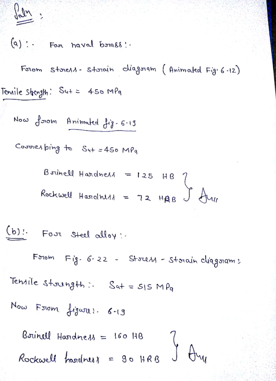
(30 points) Using the chart given below, calculate the strength in psi and in MPa of...
 (30 points) Using the chart given below, calculate the strength
in psi and in MPa of a piece of Steel of hardness 65HRA. Assume the
HB values given in the chart are at a load of 3000 Kg.
Hint: use the following equations to find the UTS: UTS in MPa =
3.5*HB
UTS in psi = 500*HB
1000O 10rDiamond Cubic boron nitride Boron carbide Titanium carbide Tungsten carbide Cementite Martensite 4000 9 Corundum 1400 8 -Topaz 1100 7Quartz 1000 E...
(30 points) Using the chart given below, calculate the strength
in psi and in MPa of a piece of Steel of hardness 65HRA. Assume the
HB values given in the chart are at a load of 3000 Kg.
Hint: use the following equations to find the UTS: UTS in MPa =
3.5*HB
UTS in psi = 500*HB
1000O 10rDiamond Cubic boron nitride Boron carbide Titanium carbide Tungsten carbide Cementite Martensite 4000 9 Corundum 1400 8 -Topaz 1100 7Quartz 1000 E...
HotLW Problem: Giving the engineering stress - engineering strain carve for an aluminum alloy, Calalate: 400FTTTTTTTTTT...
 HotLW Problem: Giving the engineering stress - engineering strain carve for an aluminum alloy, Calalate: 400FTTTTTTTTTT 10 psi 300 MPa 50 $ Stress (MPa) Stress (10 psi) 8 100- 10/ bd = 110m 1oof lo=50 mm 0 0 0.005 0.010 o 0.05 0. 100 . 150 .20 6 percent elongation at fracture (% elongation = ?) 2 yield strength (Tyield = ?) 3 Tensile strength (TS = ?) ♡ True stress at an engineering strain of 0.04. (I=?) 5 True...
Chapter 06, Problem 6.50 A steel alloy specimen having a rectangular cross section of dimensions 19.0...
 Chapter 06, Problem 6.50 A steel alloy specimen having a rectangular cross section of dimensions 19.0 mm x 3.2 mm (0.7480 in. x 0.1260 in.) has the stress-strain behavior shown in the Animated Figure. If this specimen is subjected to a tensile force of 100900 N (22680 lbf) then (a) Determine the amount of elastic strain induced. (b) Determine the amount of plastic strain induced. (c) If its original length is 400 mm, what will be its final length after...
1-Determine the % elongation, yield stress and ultimate tensile strength of the material tested above 2-Calculate...
 1-Determine the % elongation, yield stress and ultimate tensile
strength of the material tested above
2-Calculate the elastic modulus of the material tested above
3-If a 200mm cylindrical rod of the material tested above, with
radius 20mm, was subjected to a tensile load of 200kN, what would
the length be?
4-An underground wastewater steel pipe with 2mm walls carries an
ammonia solution of 40 g/m3. The pipe is in contact with
groundwater (assume 0 g/m3 ammonia). Determine the
diffusion rate...
1-Determine the % elongation, yield stress and ultimate tensile
strength of the material tested above
2-Calculate the elastic modulus of the material tested above
3-If a 200mm cylindrical rod of the material tested above, with
radius 20mm, was subjected to a tensile load of 200kN, what would
the length be?
4-An underground wastewater steel pipe with 2mm walls carries an
ammonia solution of 40 g/m3. The pipe is in contact with
groundwater (assume 0 g/m3 ammonia). Determine the
diffusion rate...
Question Do not round intermediate calculations. Give your final answer(s) to three significant figures. The stress-strain...
 Question Do not round intermediate calculations. Give your final answer(s) to three significant figures. The stress-strain diagram shown has been drawn from data obtained during a tensile test of a specimen. If E -27 x 10 psi, determine (a ) the modulus of resilience of the material, (b) the modulus of toughness of the material. o (ksi) 100 . 40 0%--0021 0.22 0.27 0.003 Part 1 out of 2 in. Ib/in3 References Multipart Answer Chapter: 11- Energy Methods
A cylindrical bar of ductile cast iron is subjected to reversed and rotating-bending tests, test results (i.e., S-N behavior) are shown in Animated Figure 8.21. If the bar diameter is 8.52 mm, determi...
 A cylindrical bar of ductile cast iron is subjected to reversed
and rotating-bending tests, test results (i.e., S-N
behavior) are shown in Animated Figure 8.21. If the bar diameter is
8.52 mm, determine the maximum cyclic load that may be applied to
ensure that fatigue failure will not occur. Assume a factor of
safety of 2.21 and that the distance between loadbearing points is
55.3 mm.
answer in N
We were unable to transcribe this imageReferences Cycles to failure 3.2E...
A cylindrical bar of ductile cast iron is subjected to reversed
and rotating-bending tests, test results (i.e., S-N
behavior) are shown in Animated Figure 8.21. If the bar diameter is
8.52 mm, determine the maximum cyclic load that may be applied to
ensure that fatigue failure will not occur. Assume a factor of
safety of 2.21 and that the distance between loadbearing points is
55.3 mm.
answer in N
We were unable to transcribe this imageReferences Cycles to failure 3.2E...
 Calculate the modulus of resilience for the material having the
stress-strain behavior shown in the Animated Figure 6.12.
Tensile strength 450 MPa (65,000 psi) Strain 0 Stress 0 MPA Stress 0 psi 500 70 Strain0 Stress 0 MPA Stress 0 psi 60 400 103 ps 50 MPa 40 Yield strength 250 MPa (36,000 psi) 300 40 0 200 30 200 30 20 100 20 10 100 10 0.10 0.20 0.30 0.40 Strain
Calculate the modulus of resilience for the material having the
stress-strain behavior shown in the Animated Figure 6.12.
Tensile strength 450 MPa (65,000 psi) Strain 0 Stress 0 MPA Stress 0 psi 500 70 Strain0 Stress 0 MPA Stress 0 psi 60 400 103 ps 50 MPa 40 Yield strength 250 MPa (36,000 psi) 300 40 0 200 30 200 30 20 100 20 10 100 10 0.10 0.20 0.30 0.40 Strain
 ive already gotten 2 wrong answers this is my last attempt
please be correct!!!!!!!!!!!!!!
Incorrect Consider the brass alloy the stress-strain behavior of which is shown in the Animated Fioure 2.12. A cylindrical specimen of this alloy 15 mm in diameter and 214 mm long is to be pulled in tension Calculate the force necessary to cause 0.00788 mm reduction in diameter. Assume a value of 0.35 for Poisson's ratio. 26507.1 the tolerance is +/-2% Click if you would like...
ive already gotten 2 wrong answers this is my last attempt
please be correct!!!!!!!!!!!!!!
Incorrect Consider the brass alloy the stress-strain behavior of which is shown in the Animated Fioure 2.12. A cylindrical specimen of this alloy 15 mm in diameter and 214 mm long is to be pulled in tension Calculate the force necessary to cause 0.00788 mm reduction in diameter. Assume a value of 0.35 for Poisson's ratio. 26507.1 the tolerance is +/-2% Click if you would like...
 Can someone help me with this materials problem?
Problem 7.23 Your answer is partially correct. Try again. Consider the brass alloy for which the stress-strain behavior is shown in the Animated Figure 7.12. A cylindrical specimen of this material 10.1 mm (0.3976 in.) in diameter and 98.8 mm (3.890 in.) long is pulled in tension with a force of 10200 N (2293 lbr). If it ls known that this alloy has a value for Polsson's ratio of 0.35, compute (a)...
Can someone help me with this materials problem?
Problem 7.23 Your answer is partially correct. Try again. Consider the brass alloy for which the stress-strain behavior is shown in the Animated Figure 7.12. A cylindrical specimen of this material 10.1 mm (0.3976 in.) in diameter and 98.8 mm (3.890 in.) long is pulled in tension with a force of 10200 N (2293 lbr). If it ls known that this alloy has a value for Polsson's ratio of 0.35, compute (a)...
 Table 6.3 Tensile stress-strain Data for several Hypothetical Metals to Be used with Concept Checks 6.2 and 6.4 Strain Fracture Elastic Yield Tensile Strength Modulus (GPa) Material Strength (MPa) Strength (MPa) at Fracture (MPa) 265 0.23 340 310 0.40 120 100 500 0.15 550 415 720 0.14 850 700 650 Fractures before yielding
 (30 points) Using the chart given below, calculate the strength
in psi and in MPa of a piece of Steel of hardness 65HRA. Assume the
HB values given in the chart are at a load of 3000 Kg.
Hint: use the following equations to find the UTS: UTS in MPa =
3.5*HB
UTS in psi = 500*HB
1000O 10rDiamond Cubic boron nitride Boron carbide Titanium carbide Tungsten carbide Cementite Martensite 4000 9 Corundum 1400 8 -Topaz 1100 7Quartz 1000 E...
(30 points) Using the chart given below, calculate the strength
in psi and in MPa of a piece of Steel of hardness 65HRA. Assume the
HB values given in the chart are at a load of 3000 Kg.
Hint: use the following equations to find the UTS: UTS in MPa =
3.5*HB
UTS in psi = 500*HB
1000O 10rDiamond Cubic boron nitride Boron carbide Titanium carbide Tungsten carbide Cementite Martensite 4000 9 Corundum 1400 8 -Topaz 1100 7Quartz 1000 E...
 HotLW Problem: Giving the engineering stress - engineering strain carve for an aluminum alloy, Calalate: 400FTTTTTTTTTT 10 psi 300 MPa 50 $ Stress (MPa) Stress (10 psi) 8 100- 10/ bd = 110m 1oof lo=50 mm 0 0 0.005 0.010 o 0.05 0. 100 . 150 .20 6 percent elongation at fracture (% elongation = ?) 2 yield strength (Tyield = ?) 3 Tensile strength (TS = ?) ♡ True stress at an engineering strain of 0.04. (I=?) 5 True...
 Chapter 06, Problem 6.50 A steel alloy specimen having a rectangular cross section of dimensions 19.0 mm x 3.2 mm (0.7480 in. x 0.1260 in.) has the stress-strain behavior shown in the Animated Figure. If this specimen is subjected to a tensile force of 100900 N (22680 lbf) then (a) Determine the amount of elastic strain induced. (b) Determine the amount of plastic strain induced. (c) If its original length is 400 mm, what will be its final length after...
 1-Determine the % elongation, yield stress and ultimate tensile
strength of the material tested above
2-Calculate the elastic modulus of the material tested above
3-If a 200mm cylindrical rod of the material tested above, with
radius 20mm, was subjected to a tensile load of 200kN, what would
the length be?
4-An underground wastewater steel pipe with 2mm walls carries an
ammonia solution of 40 g/m3. The pipe is in contact with
groundwater (assume 0 g/m3 ammonia). Determine the
diffusion rate...
1-Determine the % elongation, yield stress and ultimate tensile
strength of the material tested above
2-Calculate the elastic modulus of the material tested above
3-If a 200mm cylindrical rod of the material tested above, with
radius 20mm, was subjected to a tensile load of 200kN, what would
the length be?
4-An underground wastewater steel pipe with 2mm walls carries an
ammonia solution of 40 g/m3. The pipe is in contact with
groundwater (assume 0 g/m3 ammonia). Determine the
diffusion rate...
 Question Do not round intermediate calculations. Give your final answer(s) to three significant figures. The stress-strain diagram shown has been drawn from data obtained during a tensile test of a specimen. If E -27 x 10 psi, determine (a ) the modulus of resilience of the material, (b) the modulus of toughness of the material. o (ksi) 100 . 40 0%--0021 0.22 0.27 0.003 Part 1 out of 2 in. Ib/in3 References Multipart Answer Chapter: 11- Energy Methods
 A cylindrical bar of ductile cast iron is subjected to reversed
and rotating-bending tests, test results (i.e., S-N
behavior) are shown in Animated Figure 8.21. If the bar diameter is
8.52 mm, determine the maximum cyclic load that may be applied to
ensure that fatigue failure will not occur. Assume a factor of
safety of 2.21 and that the distance between loadbearing points is
55.3 mm.
answer in N
We were unable to transcribe this imageReferences Cycles to failure 3.2E...
A cylindrical bar of ductile cast iron is subjected to reversed
and rotating-bending tests, test results (i.e., S-N
behavior) are shown in Animated Figure 8.21. If the bar diameter is
8.52 mm, determine the maximum cyclic load that may be applied to
ensure that fatigue failure will not occur. Assume a factor of
safety of 2.21 and that the distance between loadbearing points is
55.3 mm.
answer in N
We were unable to transcribe this imageReferences Cycles to failure 3.2E...
Most questions answered within 3 hours.
-
When an object moves through a fluid, the fluid exerts a viscous
force F on the...
asked 1 hour ago -
Why did the observed chemistry of thallium mislead Mendelev to
place the group 13 element (Tl)...
asked 2 hours ago -
A sine wave signal is displayed on the screen of an
oscilloscope. 6 peak-to-peak divisions are...
asked 4 hours ago -
a
1500 kg car accelerates from 0 to 25 m / s in 21.0s. How much...
asked 5 hours ago -
Calculate the molarity of each of the following solutions:
(a) 30.5 g of ethanol (C2H5OH) in...
asked 5 hours ago -
1 Refer to the build-borrow-or-buy framework as a decision tree
for the Adidas company. Identify a...
asked 6 hours ago -
Problem 2: The Problem of Social Cost. A Rancher and Farmer live
side-by-side to each other....
asked 7 hours ago -
a uniform bar of weight 40N is 4 meter long. weights
on 60N and 100N are...
asked 7 hours ago -
Define Diet counceling? What are the
responsibilities of a counselor?
asked 9 hours ago -
Hey im just confused about how to put the ' A angle n' and ' S...
asked 9 hours ago -
A short essay about the WSJ article on Oreo versus Hydrox.
asked 9 hours ago -
##8. A program contains the following function definition:
##def cube(num):
##return num * num * num...
asked 9 hours ago