
Homework Answers


MATLAB CODE ==>
clear
clear all
t = 0:0.000001:0.01; %time range and samples for the plot
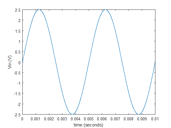
v2 = 2.5*sin(2*pi*200*t); % v+ input
v1 = 2; % v- input
k = 0;
for(tt = 0:0.000001:0.01)
k = k+1;
if(v2(k) >= v1) % comparison
vo(k) = 5;
elseif(v2(k) < v1) % comparison
vo(k) = -5;
end
end
plot(t,v2) % plot v+
figure
plot(t,vo) % plot vo
RESULTS ==>

For further help, please write in the comments.
Add Answer to:
ECE 202- Experiment 3-PreLab Homework NTROD TION TOTHE INTEG IRO T OP AMP VOLTAGE COMPARATOR 1....
Assume the op-amp below is used as a comparator circuit and that the op-amp is powered...
 Assume the op-amp below is used as a comparator circuit and that
the op-amp is powered by a bipolar
+/- 15 V power supply. If the reference voltage Vref = -9 V and the
input voltage is VI = 12 V,
determine the output voltage, VO, of the op-amp. Assume the
open-loop gain, A, is very large and
consider saturation effects. Include units in your answer.
VCC Vi V. + + Vref EE
Assume the op-amp below is used as a comparator circuit and that
the op-amp is powered by a bipolar
+/- 15 V power supply. If the reference voltage Vref = -9 V and the
input voltage is VI = 12 V,
determine the output voltage, VO, of the op-amp. Assume the
open-loop gain, A, is very large and
consider saturation effects. Include units in your answer.
VCC Vi V. + + Vref EE
1. Use supply voltage +/- 15V and design a comparator op-amp circuit where the output becomes...
1. Use supply voltage +/- 15V and design a comparator op-amp circuit where the output becomes maximum positive when the input is higher then 5V. 2. Sketch the output voltage relative to the input voltage of the circuit. 3. How can we get maximum negative output voltage when the input voltage is bigger then 5V?
9. In this ideal op amp circuit: a) Find the output voltage vo in terms of...
 9. In this ideal op amp circuit: a) Find the output voltage vo in terms of the input voltage v. b) The op amp is supplied by +10v and -10v. If0 V15v, find the range of the output voltage vo. (15 pts.) 10 k2 5 kQ 10V -10V ng 2.5v(+ 0)
Problem 3 (Op Amps) 15 1520 = 50 points R Assume the op-amp is ideal and...
 Problem 3 (Op Amps) 15 1520 = 50 points R Assume the op-amp is ideal and a load is modeled as a current source IL. This circuit R allows us to set the voltage across the load as well as monitor its current. Vin, Vo, and R are R R known quantities, but the load characteristics of VL and II are unknown. (a) What is Vi as a function of vin, Vo, and V Vin R? (b) What is Ii...
For the amplifier circuits in Figs.3 and 7: a. Write an expression for the output voltage,...
 For the amplifier circuits in Figs.3 and 7:
a. Write an expression for the output voltage, vo, in terms of
the resistor symbols and the input voltage, vin.
---For the first circuit (Fig. 3), the feedback resistor is the
series combination of R2 and R3. Use both of these resistor symbols
in your expression.
-- For circuit 2 (Fig. 7), assume that vin = 5V and ignore
potentiometer R1 and C3.
b. Using resistor values and input voltage amplitudes, calculate...
For the amplifier circuits in Figs.3 and 7:
a. Write an expression for the output voltage, vo, in terms of
the resistor symbols and the input voltage, vin.
---For the first circuit (Fig. 3), the feedback resistor is the
series combination of R2 and R3. Use both of these resistor symbols
in your expression.
-- For circuit 2 (Fig. 7), assume that vin = 5V and ignore
potentiometer R1 and C3.
b. Using resistor values and input voltage amplitudes, calculate...
Problem 7 (CLO 3, 4, 11 - Ideal Op-Amps, Design): We will now design an Op-Amp...
 Problem 7 (CLO 3, 4, 11 - Ideal Op-Amps, Design): We will now design an Op-Amp circuit to perform the function where v1 - input voltage 1, input voltage 2, = input voltage 3, Vo = output voltage. It may be helpful to consult your recitation 6 (week 7) results as well as Table 4-3 for this problem. 7.a: Select an Op-Amp configuration for your design. Sketch the Op-Amp configuration with symbolic resistors (Rf, Ri, R2, etc) indicated. Do not...
c) In estimating DC imperfections (input offset voltage, input offset current and the inverting amplifier with...
 c) In estimating DC imperfections (input offset voltage, input offset current and the inverting amplifier with nominal gain of -100 using 1 current) of an op-map, an and 10MQ resistors is implemented using the op-amp as shown in Fig 2(a) below R2 10MQ R 100k Vi Vo Figure 2(a): Inverting amplifier Measurements are conducted on the output voltage of the inverting amplifier under the following conditions: (i) the input (V) is open circuited and the output voltage is found to...
QUESTION 1. (15 points) GIVEN THE INPUT WAVEFORMS, ASSUMING VOLTAGE VOur IDEAL OP AMP. DRAN THE OUTPUT IVEN THE INPUT WAVE A. DRAW THE OUTPUT VOLTAGE Voor ON TOP OF INPUT SIGNAL V +V B. DRAW THE...
 QUESTION 1. (15 points) GIVEN THE INPUT WAVEFORMS, ASSUMING VOLTAGE VOur IDEAL OP AMP. DRAN THE OUTPUT IVEN THE INPUT WAVE A. DRAW THE OUTPUT VOLTAGE Voor ON TOP OF INPUT SIGNAL V +V B. DRAW THE OUTPUT VOLTAGE Vour ON TOP OF INPUT SIGNAL V +V +V Vi. C. HOW MUCH VOLTAGE WOULD HAVE TO BE AT THE POTENTIOMETER IN ORDER TO STABILIZE THE OUTPUT AT EXACTLY 0 VOLTS? +12 V +12 V V) Voltmeter 12 V 5V -12V...
Need part 2. 3. In following circuit, (1) Assume the Op Amp is ideal, Ri= 10...
 Need part 2.
3. In following circuit, (1) Assume the Op Amp is ideal, Ri= 10 k 2, R2 = 20 k 2, R;= 10 k 2 and R = 30 k12, find the voltage gain Vo/Vi and input resistance R. (8 pts) (2) Assume the Op Amp is not ideal, and the open-loop gain is As, R = 10 k 2, R2 = 20 k 2, R;= 10 ks2 and Ri= 30 ks2, find the voltage gain Vo/Vi and...
Need part 2.
3. In following circuit, (1) Assume the Op Amp is ideal, Ri= 10 k 2, R2 = 20 k 2, R;= 10 k 2 and R = 30 k12, find the voltage gain Vo/Vi and input resistance R. (8 pts) (2) Assume the Op Amp is not ideal, and the open-loop gain is As, R = 10 k 2, R2 = 20 k 2, R;= 10 ks2 and Ri= 30 ks2, find the voltage gain Vo/Vi and...
A. (10 pts) Implement the voltage amplifier shown below using an ideal op amp circuit. You have o...
 a. (10 pts) Implement the voltage amplifier shown below using an ideal op amp circuit. You have one op amp available for this circuit, and a range of resistors with values from 1 kΩ to 100 ka. Draw the schematic of your op amp circuit, labeling resistor values. Make sure the gain, input resistance, and output resistance of your circuit matches the model in the schematic. R=012 *100v, RL 100 b. (5 pts) Your amplifier circuit should have a frequency...
 Assume the op-amp below is used as a comparator circuit and that
the op-amp is powered by a bipolar
+/- 15 V power supply. If the reference voltage Vref = -9 V and the
input voltage is VI = 12 V,
determine the output voltage, VO, of the op-amp. Assume the
open-loop gain, A, is very large and
consider saturation effects. Include units in your answer.
VCC Vi V. + + Vref EE
Assume the op-amp below is used as a comparator circuit and that
the op-amp is powered by a bipolar
+/- 15 V power supply. If the reference voltage Vref = -9 V and the
input voltage is VI = 12 V,
determine the output voltage, VO, of the op-amp. Assume the
open-loop gain, A, is very large and
consider saturation effects. Include units in your answer.
VCC Vi V. + + Vref EE
 9. In this ideal op amp circuit: a) Find the output voltage vo in terms of the input voltage v. b) The op amp is supplied by +10v and -10v. If0 V15v, find the range of the output voltage vo. (15 pts.) 10 k2 5 kQ 10V -10V ng 2.5v(+ 0)
 Problem 3 (Op Amps) 15 1520 = 50 points R Assume the op-amp is ideal and a load is modeled as a current source IL. This circuit R allows us to set the voltage across the load as well as monitor its current. Vin, Vo, and R are R R known quantities, but the load characteristics of VL and II are unknown. (a) What is Vi as a function of vin, Vo, and V Vin R? (b) What is Ii...
 For the amplifier circuits in Figs.3 and 7:
a. Write an expression for the output voltage, vo, in terms of
the resistor symbols and the input voltage, vin.
---For the first circuit (Fig. 3), the feedback resistor is the
series combination of R2 and R3. Use both of these resistor symbols
in your expression.
-- For circuit 2 (Fig. 7), assume that vin = 5V and ignore
potentiometer R1 and C3.
b. Using resistor values and input voltage amplitudes, calculate...
For the amplifier circuits in Figs.3 and 7:
a. Write an expression for the output voltage, vo, in terms of
the resistor symbols and the input voltage, vin.
---For the first circuit (Fig. 3), the feedback resistor is the
series combination of R2 and R3. Use both of these resistor symbols
in your expression.
-- For circuit 2 (Fig. 7), assume that vin = 5V and ignore
potentiometer R1 and C3.
b. Using resistor values and input voltage amplitudes, calculate...
 Problem 7 (CLO 3, 4, 11 - Ideal Op-Amps, Design): We will now design an Op-Amp circuit to perform the function where v1 - input voltage 1, input voltage 2, = input voltage 3, Vo = output voltage. It may be helpful to consult your recitation 6 (week 7) results as well as Table 4-3 for this problem. 7.a: Select an Op-Amp configuration for your design. Sketch the Op-Amp configuration with symbolic resistors (Rf, Ri, R2, etc) indicated. Do not...
 c) In estimating DC imperfections (input offset voltage, input offset current and the inverting amplifier with nominal gain of -100 using 1 current) of an op-map, an and 10MQ resistors is implemented using the op-amp as shown in Fig 2(a) below R2 10MQ R 100k Vi Vo Figure 2(a): Inverting amplifier Measurements are conducted on the output voltage of the inverting amplifier under the following conditions: (i) the input (V) is open circuited and the output voltage is found to...
 QUESTION 1. (15 points) GIVEN THE INPUT WAVEFORMS, ASSUMING VOLTAGE VOur IDEAL OP AMP. DRAN THE OUTPUT IVEN THE INPUT WAVE A. DRAW THE OUTPUT VOLTAGE Voor ON TOP OF INPUT SIGNAL V +V B. DRAW THE OUTPUT VOLTAGE Vour ON TOP OF INPUT SIGNAL V +V +V Vi. C. HOW MUCH VOLTAGE WOULD HAVE TO BE AT THE POTENTIOMETER IN ORDER TO STABILIZE THE OUTPUT AT EXACTLY 0 VOLTS? +12 V +12 V V) Voltmeter 12 V 5V -12V...
 Need part 2.
3. In following circuit, (1) Assume the Op Amp is ideal, Ri= 10 k 2, R2 = 20 k 2, R;= 10 k 2 and R = 30 k12, find the voltage gain Vo/Vi and input resistance R. (8 pts) (2) Assume the Op Amp is not ideal, and the open-loop gain is As, R = 10 k 2, R2 = 20 k 2, R;= 10 ks2 and Ri= 30 ks2, find the voltage gain Vo/Vi and...
Need part 2.
3. In following circuit, (1) Assume the Op Amp is ideal, Ri= 10 k 2, R2 = 20 k 2, R;= 10 k 2 and R = 30 k12, find the voltage gain Vo/Vi and input resistance R. (8 pts) (2) Assume the Op Amp is not ideal, and the open-loop gain is As, R = 10 k 2, R2 = 20 k 2, R;= 10 ks2 and Ri= 30 ks2, find the voltage gain Vo/Vi and...
 a. (10 pts) Implement the voltage amplifier shown below using an ideal op amp circuit. You have one op amp available for this circuit, and a range of resistors with values from 1 kΩ to 100 ka. Draw the schematic of your op amp circuit, labeling resistor values. Make sure the gain, input resistance, and output resistance of your circuit matches the model in the schematic. R=012 *100v, RL 100 b. (5 pts) Your amplifier circuit should have a frequency...
Most questions answered within 3 hours.
-
1. In a labor market, marginal cost for a firm is
____________.
a. recruiting cost
b....
asked 31 minutes ago -
On January 1, 2019, ABC Company issued $60,000,000 of 20-year,
10.5% bonds when the market rate...
asked 55 minutes ago -
39.4% of US homes continue to use a landline in addition to cell
phone service. 3...
asked 1 hour ago -
Starting with benzene, synthesize 1-phenyl-1-butyne.
Show intermediates and reagents.
asked 2 hours ago -
Create a 32-run crossed array design with six control factors
and two noise factors such that...
asked 3 hours ago -
A 500g sample of sand from source A has the following amounts
retained on each sieve....
asked 3 hours ago -
In
your own words, please explain the essay by John Keynes wrote "The
End of Laissez...
asked 3 hours ago -
How are the matrix and pixels related? Why are smaller
pixels better for diagnostic quality?
asked 3 hours ago -
2. An AC generator has 80 rectangular loops on
its armature. Each loop is 11 cm...
asked 3 hours ago -
Please help me with this question. Consider Aldi’s current and
potential geographic markets (see Exhibit 4...
asked 3 hours ago -
What are the main components of the fermentation process and
give an explanation of each? Include...
asked 3 hours ago -
Explain which types of cells in the body (belonging to which
organs, etc.) are sensitive to...
asked 3 hours ago