

 Do all questions that are wrong or unfilled
and please circle answers
Do all questions that are wrong or unfilled
and please circle answers
Homework Answers

Add Answer to:
Do all questions that are wrong or unfilled
and please circle answers
Chapter 12, Reserve Problem...
Part The cylinder consists of spirally wrapped steel plates that are welded at the seams in...
 Part The cylinder consists of spirally wrapped steel plates that are welded at the seams in the orlentation shown. Assume 35, The cylinder has an Inslde diameter of 33 in. and a wall thickness of 0.3750 in. The end of the cylinder is capped by a rigld end plate. The cylinder is subjected to a nompressive load af P-80 kips and a torque of T-210 kip-ft, which are applied to the rigid and can in the directions shown. Datermina: (a)...
please show how they got the answers also please show how they found Qh becuse it...
 please show how they got the answers also please show how they
found Qh becuse it is not given.
scenes M15.2 Principal stresses in a tee beam The inverted tee shape is subjected to a transverse shear force of V = 110 kN and a bending moment of M = 50 kN-m, each acting in the directions shown. Determine the bending stress, the transverse shear stress magnitude, the principal stresses, and the maximum shear stress acting at location H. 14...
please show how they got the answers also please show how they
found Qh becuse it is not given.
scenes M15.2 Principal stresses in a tee beam The inverted tee shape is subjected to a transverse shear force of V = 110 kN and a bending moment of M = 50 kN-m, each acting in the directions shown. Determine the bending stress, the transverse shear stress magnitude, the principal stresses, and the maximum shear stress acting at location H. 14...
Chapter 12, Supplemental Question 049 (GO Tutorial) and show them on a stress element. as shown....
 Chapter 12, Supplemental Question 049 (GO Tutorial) and show them on a stress element. as shown. Determine the normal and shear stresses at point 200 N m and an axial tension load of ρ-22 k A 39-mm-diameter solid shaft is subjected to both a torque of T Answers: MPa MPa MPa ay
A column with a wide-flange section has a flange width b = 400 mm , height...
 A column with a wide-flange section has a flange width
b = 400 mm , height h = 400 mm , web thickness
tw = 13 mm , and flange thickness
tf = 21 mm (Figure 1). Calculate the stresses at
a point 65 mm above the neutral axis if the section supports a
tensile normal force N = 3 kN at the centroid, shear force
V = 7.4 kN , and bending moment M = 4 kN⋅m as
shown...
A column with a wide-flange section has a flange width
b = 400 mm , height h = 400 mm , web thickness
tw = 13 mm , and flange thickness
tf = 21 mm (Figure 1). Calculate the stresses at
a point 65 mm above the neutral axis if the section supports a
tensile normal force N = 3 kN at the centroid, shear force
V = 7.4 kN , and bending moment M = 4 kN⋅m as
shown...
The beam shown (Figure 1) is supported by a pin at A and a cable at...
 The beam shown (Figure 1) is
supported by a pin at A and a cable at B. Two
loads P = 13 kN are applied straight down from the
centerline of the bottom face. Determine the state of stress at the
point shown (Figure 2) in a section 2 m from the wall. The
dimensions are w = 5.2 cm , h = 10.5 cm ,
L = 0.8 m , a = 1.5 cm , and b = 4...
The beam shown (Figure 1) is
supported by a pin at A and a cable at B. Two
loads P = 13 kN are applied straight down from the
centerline of the bottom face. Determine the state of stress at the
point shown (Figure 2) in a section 2 m from the wall. The
dimensions are w = 5.2 cm , h = 10.5 cm ,
L = 0.8 m , a = 1.5 cm , and b = 4...
The beam shown (Figure 1) is supported by a pin at A and a cable at...
 The beam shown (Figure 1) is supported by a pin at A
and a cable at B. Two loads P = 13 kN are applied
straight down from the centerline of the bottom face. Determine the
state of stress at the point shown (Figure 2) in a section 2 m from
the wall. The dimensions are w = 5.2 cm , h =
10.5 cm , L = 0.8 m , a = 1.5 cm , and b
= 4...
The beam shown (Figure 1) is supported by a pin at A
and a cable at B. Two loads P = 13 kN are applied
straight down from the centerline of the bottom face. Determine the
state of stress at the point shown (Figure 2) in a section 2 m from
the wall. The dimensions are w = 5.2 cm , h =
10.5 cm , L = 0.8 m , a = 1.5 cm , and b
= 4...
The beam shown (Figure 1) is supported by a pin at A and a cable at...
 The beam shown (Figure 1) is supported by a pin at A and a cable at
B. Two loads P = 13 kN are applied straight down
from the centerline of the bottom face. Determine the state of
stress at the point shown (Figure 2) in a section 2 m from the
wall. The dimensions are w = 5.2 cm , h = 10.5 cm
, L = 0.8 m , a = 1.5 cm , and b = 4...
The beam shown (Figure 1) is supported by a pin at A and a cable at
B. Two loads P = 13 kN are applied straight down
from the centerline of the bottom face. Determine the state of
stress at the point shown (Figure 2) in a section 2 m from the
wall. The dimensions are w = 5.2 cm , h = 10.5 cm
, L = 0.8 m , a = 1.5 cm , and b = 4...
Aroadway sign that weighs Py = 12 kN is supported by a structural pipe with an...
 Aroadway sign that weighs Py = 12 kN is supported by a structural pipe with an outside diameter of 300 mm and a wall thickness of 12.5 mm. Wind pressure on the sign creates a resultant force of P, - 18 kN, acting as shown. Using length dimensions of a = 4.5 m and b = 6.1 m, determine (a) the normal and shear stresses at point H. (b) the normal and shear stresses at point K. P. H K...
Learning Goal: The beam shown (Figure 1) is supported by a pin at A and a...
 Learning Goal: The beam shown (Figure 1) is supported by a pin at A and a cable at B. Two loads P = 18 kN are applied straight down from the centerline of the bottom face. Determine the state of stress at the point shown (Figure 2) in a section 2 m from the wall. The dimensions are w = 5.4 cm , h = 12 cm, L = 0.8 m, a = 1.5 cm , and b = 4...
The cantilever beam of length 3L is subject to concentrated loads P and 2P and has...
 The cantilever beam of length 3L is subject to concentrated loads P and 2P and has the thin-walled cross-section illustrated below. The cross-section has uniform thickness t and moment of inertia with respect to the centroidal z-axis given by I = 3140 t4. Use t = 5 mm, L = 135 mm and P= 6 kN. 2P H 10 t 5t A P 10 t 22 L 10 t 1) Determine the numerical value of the shear force and bending...
 Part The cylinder consists of spirally wrapped steel plates that are welded at the seams in the orlentation shown. Assume 35, The cylinder has an Inslde diameter of 33 in. and a wall thickness of 0.3750 in. The end of the cylinder is capped by a rigld end plate. The cylinder is subjected to a nompressive load af P-80 kips and a torque of T-210 kip-ft, which are applied to the rigid and can in the directions shown. Datermina: (a)...
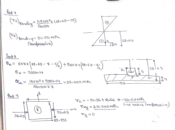
 please show how they got the answers also please show how they
found Qh becuse it is not given.
scenes M15.2 Principal stresses in a tee beam The inverted tee shape is subjected to a transverse shear force of V = 110 kN and a bending moment of M = 50 kN-m, each acting in the directions shown. Determine the bending stress, the transverse shear stress magnitude, the principal stresses, and the maximum shear stress acting at location H. 14...
please show how they got the answers also please show how they
found Qh becuse it is not given.
scenes M15.2 Principal stresses in a tee beam The inverted tee shape is subjected to a transverse shear force of V = 110 kN and a bending moment of M = 50 kN-m, each acting in the directions shown. Determine the bending stress, the transverse shear stress magnitude, the principal stresses, and the maximum shear stress acting at location H. 14...
 Chapter 12, Supplemental Question 049 (GO Tutorial) and show them on a stress element. as shown. Determine the normal and shear stresses at point 200 N m and an axial tension load of ρ-22 k A 39-mm-diameter solid shaft is subjected to both a torque of T Answers: MPa MPa MPa ay
 A column with a wide-flange section has a flange width
b = 400 mm , height h = 400 mm , web thickness
tw = 13 mm , and flange thickness
tf = 21 mm (Figure 1). Calculate the stresses at
a point 65 mm above the neutral axis if the section supports a
tensile normal force N = 3 kN at the centroid, shear force
V = 7.4 kN , and bending moment M = 4 kN⋅m as
shown...
A column with a wide-flange section has a flange width
b = 400 mm , height h = 400 mm , web thickness
tw = 13 mm , and flange thickness
tf = 21 mm (Figure 1). Calculate the stresses at
a point 65 mm above the neutral axis if the section supports a
tensile normal force N = 3 kN at the centroid, shear force
V = 7.4 kN , and bending moment M = 4 kN⋅m as
shown...
 The beam shown (Figure 1) is
supported by a pin at A and a cable at B. Two
loads P = 13 kN are applied straight down from the
centerline of the bottom face. Determine the state of stress at the
point shown (Figure 2) in a section 2 m from the wall. The
dimensions are w = 5.2 cm , h = 10.5 cm ,
L = 0.8 m , a = 1.5 cm , and b = 4...
The beam shown (Figure 1) is
supported by a pin at A and a cable at B. Two
loads P = 13 kN are applied straight down from the
centerline of the bottom face. Determine the state of stress at the
point shown (Figure 2) in a section 2 m from the wall. The
dimensions are w = 5.2 cm , h = 10.5 cm ,
L = 0.8 m , a = 1.5 cm , and b = 4...
 The beam shown (Figure 1) is supported by a pin at A
and a cable at B. Two loads P = 13 kN are applied
straight down from the centerline of the bottom face. Determine the
state of stress at the point shown (Figure 2) in a section 2 m from
the wall. The dimensions are w = 5.2 cm , h =
10.5 cm , L = 0.8 m , a = 1.5 cm , and b
= 4...
The beam shown (Figure 1) is supported by a pin at A
and a cable at B. Two loads P = 13 kN are applied
straight down from the centerline of the bottom face. Determine the
state of stress at the point shown (Figure 2) in a section 2 m from
the wall. The dimensions are w = 5.2 cm , h =
10.5 cm , L = 0.8 m , a = 1.5 cm , and b
= 4...
 The beam shown (Figure 1) is supported by a pin at A and a cable at
B. Two loads P = 13 kN are applied straight down
from the centerline of the bottom face. Determine the state of
stress at the point shown (Figure 2) in a section 2 m from the
wall. The dimensions are w = 5.2 cm , h = 10.5 cm
, L = 0.8 m , a = 1.5 cm , and b = 4...
The beam shown (Figure 1) is supported by a pin at A and a cable at
B. Two loads P = 13 kN are applied straight down
from the centerline of the bottom face. Determine the state of
stress at the point shown (Figure 2) in a section 2 m from the
wall. The dimensions are w = 5.2 cm , h = 10.5 cm
, L = 0.8 m , a = 1.5 cm , and b = 4...
 Aroadway sign that weighs Py = 12 kN is supported by a structural pipe with an outside diameter of 300 mm and a wall thickness of 12.5 mm. Wind pressure on the sign creates a resultant force of P, - 18 kN, acting as shown. Using length dimensions of a = 4.5 m and b = 6.1 m, determine (a) the normal and shear stresses at point H. (b) the normal and shear stresses at point K. P. H K...
 Learning Goal: The beam shown (Figure 1) is supported by a pin at A and a cable at B. Two loads P = 18 kN are applied straight down from the centerline of the bottom face. Determine the state of stress at the point shown (Figure 2) in a section 2 m from the wall. The dimensions are w = 5.4 cm , h = 12 cm, L = 0.8 m, a = 1.5 cm , and b = 4...
 The cantilever beam of length 3L is subject to concentrated loads P and 2P and has the thin-walled cross-section illustrated below. The cross-section has uniform thickness t and moment of inertia with respect to the centroidal z-axis given by I = 3140 t4. Use t = 5 mm, L = 135 mm and P= 6 kN. 2P H 10 t 5t A P 10 t 22 L 10 t 1) Determine the numerical value of the shear force and bending...
Most questions answered within 3 hours.
-
Determine the temperature (in Celsius) at which 1.00 mole of an
ideal gas will have a...
asked 14 minutes ago -
Japan’s combination of X and Y
Canada’s combination of X and Y
100x and 0y
50x...
asked 7 minutes ago -
[1] Household statistics include individuals living alone or in
groups in:
A) apartments.
B) military barracks....
asked 17 minutes ago -
What is the % w/v when 80 mL of a 2.0% solution is mixed with 50...
asked 21 minutes ago -
How can I solve the following using a TI83
Claim: Most adults would erase all of...
asked 33 minutes ago -
Analysis of 3-ethyl-3-buten-2-ol gave C, 72.13%; H, 11.92%.
Calculate the percent deviation of these results from...
asked 30 minutes ago -
Which VALS segment is most likely to have a top of the line
brand new (2015)...
asked 34 minutes ago -
Write a program to score the paper-rock-scissor game. Each of
two users types in either P,R...
asked 54 minutes ago -
Calculate the equillibrium constent K for a redox reaction that
has E°cell = -.98 V at...
asked 1 hour ago -
A concave spherical mirror has a radius of curvature of
magnitude 19.6 cm.
(a) Find the...
asked 1 hour ago -
3. draw a diagram of the magnetic field:
a. around a long straight wire with a...
asked 1 hour ago -
If you titrated 30.0 mL of 0.1 M HCl with 0.1 M NaOH, indicate
the approximate...
asked 1 hour ago