
Homework Answers


Add Answer to:
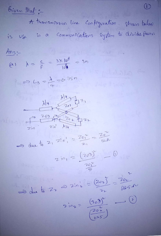
Problem 2 A transmission line configuration, shown below, is use in a communications system to divide...
Question 3-100 Marks Time Domain Reflectometry A transmission line is created from spare equipmen...
 Question 3-100 Marks Time Domain Reflectometry A transmission line is created from spare equipment at hand but has mis-matched impedances. The equivalent circuit is shown in the diagram following. It has source of internal resistance, Zi, is driving a load, z, via a length, d, of lossless 75Ω coaxial cable, Zo. The source voltage is initially zero and the line is initially uncharged, with NEr 2.8 Z1 Vi 7o ZL 0 coaxial cable Table 3: Values for Calculations Last Student...
ossless transmission line is terminated with a short circuit at the far end as shown in the figure below. Calculate the input impedance Zin a) at dc; 2) A l b) when the line is # long; when the l...
 ossless transmission line is terminated with a short circuit at the far end as shown in the figure below. Calculate the input impedance Zin a) at dc; 2) A l b) when the line is # long; when the line is 4 long; c) d) when the line is long. Based on the previous results, plot the imaginary part of the input impedance as a function of e) the electrical length of the line. -0 Zo Zin
ossless transmission line...
ossless transmission line is terminated with a short circuit at the far end as shown in the figure below. Calculate the input impedance Zin a) at dc; 2) A l b) when the line is # long; when the line is 4 long; c) d) when the line is long. Based on the previous results, plot the imaginary part of the input impedance as a function of e) the electrical length of the line. -0 Zo Zin
ossless transmission line...
Please answer ASAP Problem 2 (35 points) For the transmission line circuit shown below, the voltage...
 Please answer ASAP
Problem 2 (35 points) For the transmission line circuit shown below, the voltage at the load is given by, vLCt)2 cos(ot +180°) v (a) Calculate the time-averaged power delivered to the load. (5 points) (b) Determine the generator voltage vs(t).(20 points) (c) Calculate the time-averaged power supplied by the generator.(10 points) 75 2 Zo-50 Ω
Please answer ASAP
Problem 2 (35 points) For the transmission line circuit shown below, the voltage at the load is given by, vLCt)2 cos(ot +180°) v (a) Calculate the time-averaged power delivered to the load. (5 points) (b) Determine the generator voltage vs(t).(20 points) (c) Calculate the time-averaged power supplied by the generator.(10 points) 75 2 Zo-50 Ω
Assume a round-rotor generator delivering power in the steady state to a load bus through two transformers and a transmission line. The topology of the system is shown as below XL Хо Xi/2 XP Figure Q...
 Assume a round-rotor generator delivering power in the steady state to a load bus through two transformers and a transmission line. The topology of the system is shown as below XL Хо Xi/2 XP Figure Q5 Parameters are as follows: G: Xgi -0.10 TI: Х,1-0, 10 12: XT2-0.20 0.40 Initial state: E1-1 .6 ,見= 1.6 (a) Please determine the maximal real power that can be delivered through the transmission system. (b) Please determine 6 at the steady state. (c) Assume...
 Question 3-100 Marks Time Domain Reflectometry A transmission line is created from spare equipment at hand but has mis-matched impedances. The equivalent circuit is shown in the diagram following. It has source of internal resistance, Zi, is driving a load, z, via a length, d, of lossless 75Ω coaxial cable, Zo. The source voltage is initially zero and the line is initially uncharged, with NEr 2.8 Z1 Vi 7o ZL 0 coaxial cable Table 3: Values for Calculations Last Student...
 ossless transmission line is terminated with a short circuit at the far end as shown in the figure below. Calculate the input impedance Zin a) at dc; 2) A l b) when the line is # long; when the line is 4 long; c) d) when the line is long. Based on the previous results, plot the imaginary part of the input impedance as a function of e) the electrical length of the line. -0 Zo Zin
ossless transmission line...
ossless transmission line is terminated with a short circuit at the far end as shown in the figure below. Calculate the input impedance Zin a) at dc; 2) A l b) when the line is # long; when the line is 4 long; c) d) when the line is long. Based on the previous results, plot the imaginary part of the input impedance as a function of e) the electrical length of the line. -0 Zo Zin
ossless transmission line...
 Please answer ASAP
Problem 2 (35 points) For the transmission line circuit shown below, the voltage at the load is given by, vLCt)2 cos(ot +180°) v (a) Calculate the time-averaged power delivered to the load. (5 points) (b) Determine the generator voltage vs(t).(20 points) (c) Calculate the time-averaged power supplied by the generator.(10 points) 75 2 Zo-50 Ω
Please answer ASAP
Problem 2 (35 points) For the transmission line circuit shown below, the voltage at the load is given by, vLCt)2 cos(ot +180°) v (a) Calculate the time-averaged power delivered to the load. (5 points) (b) Determine the generator voltage vs(t).(20 points) (c) Calculate the time-averaged power supplied by the generator.(10 points) 75 2 Zo-50 Ω
 Assume a round-rotor generator delivering power in the steady state to a load bus through two transformers and a transmission line. The topology of the system is shown as below XL Хо Xi/2 XP Figure Q5 Parameters are as follows: G: Xgi -0.10 TI: Х,1-0, 10 12: XT2-0.20 0.40 Initial state: E1-1 .6 ,見= 1.6 (a) Please determine the maximal real power that can be delivered through the transmission system. (b) Please determine 6 at the steady state. (c) Assume...
Most questions answered within 3 hours.
-
----Can someone please help me solve this one using JAVA
----I thank you in advance
Create...
asked 2 minutes ago -
) Raw materials are studied for contamination. Suppose that
the number of particles of contamination per...
asked 1 minute ago -
1. What force primarily attracts the potassium ion to
the nitrate ion?
a. London forces...
asked 4 minutes ago -
What are the negative effects of abruptly stopping the use of
all fossil fuels? Give at...
asked 10 minutes ago -
Given that many conflict are the result of different parties having
different interests, is it possible...
asked 15 minutes ago -
A 750 g block can slide uniformly along the horizontal track
when a string attached to...
asked 18 minutes ago -
In 2017, Juan entered into a contract to write a book. The
publisher advanced Juan $50,000,...
asked 32 minutes ago -
Determine the number of kinds of protons in each molecule (w/
respect to NMR spectroscopy). Drawing...
asked 42 minutes ago -
A jeweler whose near point is 68 cm from his eye uses a
magnifying glass as...
asked 40 minutes ago -
A company wants to determine how many units of each of two
products, A and B,...
asked 44 minutes ago -
The blood pressure of a person changes throughout the day.
Suppose the systolic blood pressure of...
asked 53 minutes ago -
A chemistry student desired to study sulfur. Sulfur exhibited
the following characteristics with oxygen:
(a) It...
asked 49 minutes ago