
Homework Answers
Add Answer to:
P.2 The reservoirs in Fig. are connected by cast-iron pipes (e=0.00015ft) joined abruptly, with sharp-edged entrance...
Two water reservoirs A and B are connected to each other through a 35m-long, 2-cm-diameter cast...
 Two water reservoirs A and B are connected to each other through a 35m-long, 2-cm-diameter cast iron pipe with a sharp-edged entrance. The pipe also involves a swing check valve and a fully open gate valve. The water level in both reservoirs is the same, but reservoir A is pressurized by compressed air while reservoir B is open to the atmosphere at 94 kPa. If the initial flow rate through the pipe is 1.2 L/s, determine the air pressure (gage)...
4. Figure 2 shows two reservoirs which are connected by three pipes of different diameters. The...
 4. Figure 2 shows two reservoirs which are connected by three pipes of different diameters. The length and diameter of each pipe are given in Table 1. The flow rate in the pipeline is 55 Ls. The entrance and exit from the pipes are sharp and the change between the pipelines in the cross sections is sudden. Assume the friction factor, /for the pipes as 0.01. (a) Analyse all the head losses which occur, giving an expression for each. (7...
In the given figure, the pipe entrance is sharp-edged. The elevation at the entrance is Az...
 In the given figure, the pipe entrance is sharp-edged. The elevation at the entrance is Az 44 m. If the flow rate is 0.004 m3/s, what power in Wis extracted by the turbine? For water at 20 "C, take p 998 kg/m3 and ? 0.001 kgm s. For cast on take ? ~ 0.26 mm. The minor loss coefficients are Entrance: 0.5; 5-cm 2 open globe valve: K-6.9 Take ?-227 For the given flow. take f 0.0316. Round the answer...
fluid mechanics ASAP please Problem 4 (50 points) Water is discharged from a reservoir at a rate of 18.103 m3/s using two horizontal cast iron pipes connected in series and a pump between them. T...
 fluid mechanics
ASAP please
Problem 4 (50 points) Water is discharged from a reservoir at a rate of 18.103 m3/s using two horizontal cast iron pipes connected in series and a pump between them. The first pipe is 20 m long and has a 6-cm diameter, while the second pipe is 35 m long and has a 4-cm diameter. The water level in the reservoir is 30 m above the centerline of the pipe. The pipe entrance is sharp-edged. Losses...
fluid mechanics
ASAP please
Problem 4 (50 points) Water is discharged from a reservoir at a rate of 18.103 m3/s using two horizontal cast iron pipes connected in series and a pump between them. The first pipe is 20 m long and has a 6-cm diameter, while the second pipe is 35 m long and has a 4-cm diameter. The water level in the reservoir is 30 m above the centerline of the pipe. The pipe entrance is sharp-edged. Losses...
2) In the Figure below, the pipe entrance is sharp-edged. If the flow rate is 0.004...
 2) In the Figure below, the pipe entrance is sharp-edged. If the flow rate is 0.004 m3/s, what power, in W, is extracted by the turbine? (For water at 20°C, take ρ-998 kg/m3 and μ 0.001 kg/ms. For cast iron, take ε ~ 0.26 mm) Open globe valve Turbine 40 m Water Cast iron: L 125 m, D 5 cm
As shown in the figure we are dealing with a pipe system in which there are...
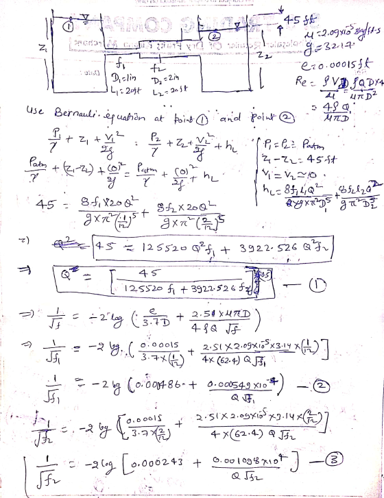
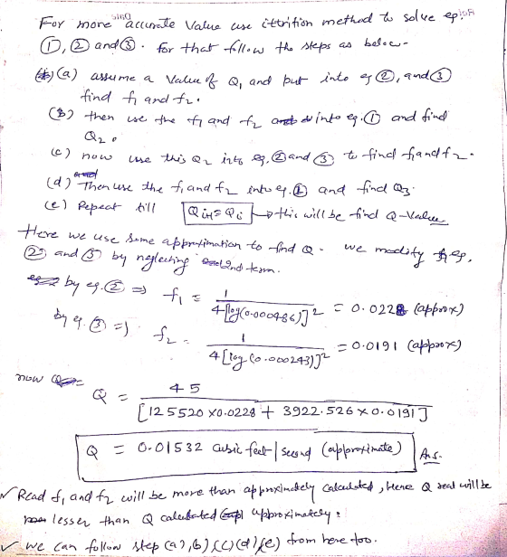
 As shown in the figure we are dealing with a pipe system in which there are 125 ft of 2-in pipe, 75 ft of 6-in pipe, and 150 ft of 3-in pipe, all cast iron. There are two 90° elbows and an open globe valve. If the exit elevation is zero, what horsepower is extracted by the turbine when the flow rate is 0.16 ft3/s of water at 20°C? Elevation 100 sudden expansion from 2" to 3": KL =0.79 2...
2. Water flows at a rate of 60 L/s from a main reservoir to a subsidiary...
 2. Water flows at a rate of 60 L/s from a main reservoir to a subsidiary through a 600 m long, 185 mm diameter asphalted cast iron pipe as shown in the figure. The pipeline contains a gate valve, a globe valve and 4 standard 90° elbows. The entrance and exit are square edged, and all fittings are screwed ends, determine, You need Kinematic viscosity of water, 1 x 10⁻⁶ m/s2 (a) The friction head loss in the pipe, (b)...
Problem 4 (50 points) water is discharged from a reservoir at a rate of 18.103 m2/s using two horizontal cast iron pipes nected in series and a pump between them. The first pipe is 20 m long and...
 Problem 4 (50 points) water is discharged from a reservoir at a rate of 18.103 m2/s using two horizontal cast iron pipes nected in series and a pump between them. The first pipe is 20 m long and has a 6-cm diameter, while the second pipe is 35 m long and has a 4-cm diameter. The water level in the reservoir is 30 m above the centerline of the pipe. The pipe entrance is sharp-edged. Losses associated with the connection...
Two reservoirs are connected using the piping network shown in the figure. The pipes are commerci...
 Two reservoirs are connected using the piping network shown in
the figure. The pipes are commercial steel. Water is to be pumped
using a pump (efficiency = 70%) that draws 8 kW of electric power
from the mains. Ignore minor losses. Determine the flow rate
through each pipe and the total flow between the reservoirs. Start
with a friction factor of 0.02 for all pipes and use the Haaland
equation to calculate updated friction factors. Ignore the length
of the...
Two reservoirs are connected using the piping network shown in
the figure. The pipes are commercial steel. Water is to be pumped
using a pump (efficiency = 70%) that draws 8 kW of electric power
from the mains. Ignore minor losses. Determine the flow rate
through each pipe and the total flow between the reservoirs. Start
with a friction factor of 0.02 for all pipes and use the Haaland
equation to calculate updated friction factors. Ignore the length
of the...
 Two water reservoirs A and B are connected to each other through a 35m-long, 2-cm-diameter cast iron pipe with a sharp-edged entrance. The pipe also involves a swing check valve and a fully open gate valve. The water level in both reservoirs is the same, but reservoir A is pressurized by compressed air while reservoir B is open to the atmosphere at 94 kPa. If the initial flow rate through the pipe is 1.2 L/s, determine the air pressure (gage)...
 Two water reservoirs A and B are connected to each other through a 35m-long, 2-cm-diameter cast iron pipe with a sharp-edged entrance. The pipe also involves a swing check valve and a fully open gate valve. The water level in both reservoirs is the same, but reservoir A is pressurized by compressed air while reservoir B is open to the atmosphere at 94 kPa. If the initial flow rate through the pipe is 1.2 L/s, determine the air pressure (gage)...
 4. Figure 2 shows two reservoirs which are connected by three pipes of different diameters. The length and diameter of each pipe are given in Table 1. The flow rate in the pipeline is 55 Ls. The entrance and exit from the pipes are sharp and the change between the pipelines in the cross sections is sudden. Assume the friction factor, /for the pipes as 0.01. (a) Analyse all the head losses which occur, giving an expression for each. (7...
 In the given figure, the pipe entrance is sharp-edged. The elevation at the entrance is Az 44 m. If the flow rate is 0.004 m3/s, what power in Wis extracted by the turbine? For water at 20 "C, take p 998 kg/m3 and ? 0.001 kgm s. For cast on take ? ~ 0.26 mm. The minor loss coefficients are Entrance: 0.5; 5-cm 2 open globe valve: K-6.9 Take ?-227 For the given flow. take f 0.0316. Round the answer...
 fluid mechanics
ASAP please
Problem 4 (50 points) Water is discharged from a reservoir at a rate of 18.103 m3/s using two horizontal cast iron pipes connected in series and a pump between them. The first pipe is 20 m long and has a 6-cm diameter, while the second pipe is 35 m long and has a 4-cm diameter. The water level in the reservoir is 30 m above the centerline of the pipe. The pipe entrance is sharp-edged. Losses...
fluid mechanics
ASAP please
Problem 4 (50 points) Water is discharged from a reservoir at a rate of 18.103 m3/s using two horizontal cast iron pipes connected in series and a pump between them. The first pipe is 20 m long and has a 6-cm diameter, while the second pipe is 35 m long and has a 4-cm diameter. The water level in the reservoir is 30 m above the centerline of the pipe. The pipe entrance is sharp-edged. Losses...
 2) In the Figure below, the pipe entrance is sharp-edged. If the flow rate is 0.004 m3/s, what power, in W, is extracted by the turbine? (For water at 20°C, take ρ-998 kg/m3 and μ 0.001 kg/ms. For cast iron, take ε ~ 0.26 mm) Open globe valve Turbine 40 m Water Cast iron: L 125 m, D 5 cm
 As shown in the figure we are dealing with a pipe system in which there are 125 ft of 2-in pipe, 75 ft of 6-in pipe, and 150 ft of 3-in pipe, all cast iron. There are two 90° elbows and an open globe valve. If the exit elevation is zero, what horsepower is extracted by the turbine when the flow rate is 0.16 ft3/s of water at 20°C? Elevation 100 sudden expansion from 2" to 3": KL =0.79 2...
 2. Water flows at a rate of 60 L/s from a main reservoir to a subsidiary through a 600 m long, 185 mm diameter asphalted cast iron pipe as shown in the figure. The pipeline contains a gate valve, a globe valve and 4 standard 90° elbows. The entrance and exit are square edged, and all fittings are screwed ends, determine, You need Kinematic viscosity of water, 1 x 10⁻⁶ m/s2 (a) The friction head loss in the pipe, (b)...
 Problem 4 (50 points) water is discharged from a reservoir at a rate of 18.103 m2/s using two horizontal cast iron pipes nected in series and a pump between them. The first pipe is 20 m long and has a 6-cm diameter, while the second pipe is 35 m long and has a 4-cm diameter. The water level in the reservoir is 30 m above the centerline of the pipe. The pipe entrance is sharp-edged. Losses associated with the connection...
 Two reservoirs are connected using the piping network shown in
the figure. The pipes are commercial steel. Water is to be pumped
using a pump (efficiency = 70%) that draws 8 kW of electric power
from the mains. Ignore minor losses. Determine the flow rate
through each pipe and the total flow between the reservoirs. Start
with a friction factor of 0.02 for all pipes and use the Haaland
equation to calculate updated friction factors. Ignore the length
of the...
Two reservoirs are connected using the piping network shown in
the figure. The pipes are commercial steel. Water is to be pumped
using a pump (efficiency = 70%) that draws 8 kW of electric power
from the mains. Ignore minor losses. Determine the flow rate
through each pipe and the total flow between the reservoirs. Start
with a friction factor of 0.02 for all pipes and use the Haaland
equation to calculate updated friction factors. Ignore the length
of the...
Most questions answered within 3 hours.
-
What mechanisms Drive speciation??
(I.e. what was Dawins theory on the orgin of species, and how...
asked 3 minutes ago -
The manager at a car assembly plant believes that the mean
assembly time for a car...
asked 55 minutes ago -
Which of the following is true of electron capture?
A) It decreases the nuclide's mass number...
asked 2 hours ago -
Assuming an efficiency of 43.10%, calculate the actual yield of
magnesium nitrate formed from 114.9 g...
asked 3 hours ago -
The highly pathogenic bacterium Clostridium
perfringens causes gangrene, a disease that results in the
destruction of...
asked 4 hours ago -
In the context of situation analysis, which of the following is
a category for analysis in...
asked 4 hours ago -
In a study of the gas phase decomposition of sulfuryl chloride
at 600 K SO2Cl2(g)SO2(g) +...
asked 4 hours ago -
75 g of 2-propanol (C3H8O) and 25 g of pentane are mixed in a
200 mL...
asked 4 hours ago -
The 2800-turn coil in a dc motor has an area per turn of 1.1 ×
10-2...
asked 5 hours ago -
Draw a combinational logic circuit diagram with a symbol inside
the box for two I/P of...
asked 5 hours ago -
The cliché we use quite a lot in finance is: there is a need to
maximize...
asked 5 hours ago -
In class we discussed the addition of HCl to alpha pinene. Would
you expect one or...
asked 5 hours ago