
Homework Answers
Add Answer to:
Consider three (causal) LTI systems, corresponding to transfer functions described (except for gain K) by the...
Consider a causal LTI S9Stem whch s Characterized by the differente euation a) Determine the transfer...
 Consider a causal LTI S9Stem whch s Characterized by the differente euation a) Determine the transfer Suntion, H(z) os the b) Plot +he pole-Zero diagram for the soh d) Determ ine the impulse response os the o S9stem c) Is the system stable? Tastify your answer e) Find the response os the sostem,uhi,i the
2.6.1 Consider a causal continuous-time LTI system described by the differential equation u"(t) +...
 2.6.1-2.6.62.6.1 Consider a causal contimuous-time LTI system described by the differential equation$$ y^{\prime \prime}(t)+y(t)=x(t) $$(a) Find the transfer function \(H(s)\), its \(R O C\), and its poles.(b) Find the impulse response \(h(t)\).(c) Classify the system as stable/unstable.(d) Find the step response of the system.2.6.2 Given the impulse response of a continuous-time LTI system, find the transfer function \(H(s),\) the \(\mathrm{ROC}\) of \(H(s)\), and the poles of the system. Also find the differential equation describing each system.(a) \(h(t)=\sin (3 t) u(t)\)(b)...
For a causal LTI discrete-time system described by the difference equation:
For a causal LTI discrete-time system described by the difference equation: y[n] + y[n – 1] = x[n] a) Find the transfer function H(z).b) Find poles and zeros and then mark them on the z-plane (pole-zero plot). Is this system BIBO? c) Find its impulse response h[n]. d) Draw the z-domain block diagram (using the unit delay block z-1) of the discrete-time system. e) Find the output y[n] for input x[n] = 10 u[n] if all initial conditions are 0.
5. Consider an LTI system with transfer function H(s). Pole-zero plot of H(s) is shown below....
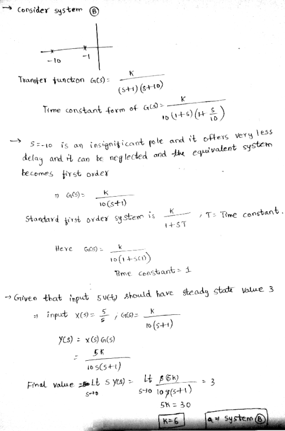
 5. Consider an LTI system with transfer function H(s). Pole-zero plot of H(s) is shown below. Im (a) How many ROCs can be considered for this system? (b) Assume system is causal. Find ROC of H(S) (c) Assume y(t) is system output with step unit as input. Given lim y(t) = 5 , 00 Find H(s).
3. Consider an LTI system with transfer function H(s). Pole-zero plot of H(s) is shown below....
 3. Consider an LTI system with transfer function H(s). Pole-zero plot of H(s) is shown below. Im O--- Re (a) How many ROCs can be considered for this system? (b) Assume system is causal. Find ROC of H(S) (c) Assume y(t) is system output with step unit as input. Given lim yết) = 5 , Find H(s). (d) (optional) Find y(2) (y(t) for t = 2).
A causal discrete-time LTI system is described by the equation
A causal discrete-time LTI system is described by the equationwhere z is the input signal, and y the output signal y(n) = 1/3x(n) + 1/3x(n -1) + 1/3x(n - 2) (a) Sketch the impulse response of the system. (b) What is the dc gain of the system? (Find Hf(0).) (c) Sketch the output of the system when the input x(n) is the constant unity signal, x(n) = 1. (d) Sketch the output of the system when the input x(n) is the unit step signal, x(n)...
4. 1 20 points). Consider a causal LTI system with a pole-zero plot for th the dfee equation H(2) as show below. The system is known to have a DC gain of 1. Find the difference equation for this...
 4. 1 20 points). Consider a causal LTI system with a pole-zero plot for th the dfee equation H(2) as show below. The system is known to have a DC gain of 1. Find the difference equation for this system. Show all work. Z - plane 0.5 -0.5 0.5e
4. 1 20 points). Consider a causal LTI system with a pole-zero plot for th the dfee equation H(2) as show below. The system is known to have a DC gain...
4. 1 20 points). Consider a causal LTI system with a pole-zero plot for th the dfee equation H(2) as show below. The system is known to have a DC gain of 1. Find the difference equation for this system. Show all work. Z - plane 0.5 -0.5 0.5e
4. 1 20 points). Consider a causal LTI system with a pole-zero plot for th the dfee equation H(2) as show below. The system is known to have a DC gain...
1. A causal LTI system is implemented by the difference equation y(n) = 2r(n) - 0.5...
 1. A causal LTI system is implemented by the difference equation y(n) = 2r(n) - 0.5 y(n-1). (a) Find the frequency response H/(w) of the system. (b) Plot the pole-zero diagram of the system. Based on the pole zero diagram, roughly sketch the frequency response magnitude |H'(w). (c) Indicate on your sketch of H w , its exact values at w=0, 0.5, and . (d) Find the output signal y(n) produced by the input signal (n) = 3 + cos(0.5...
Problem 3. The input and the output of a stable and causal LTI system are related...
 Problem 3. The input and the output of a stable and causal LTI system are related by the differential equation dy ) + 64x2 + 8y(t) = 2x(t) dt2 dt i) Find the frequency response of the system H(jw) [2 marks] ii) Using your result in (i) find the impulse response of the system h(t). [3 marks] iii) Find the transfer function of the system H(s), i.e. the Laplace transform of the impulse response [2 marks] iv) Sketch the pole-zero...
Consider a causal LTI system implemented as the RL circuit shown below. In this circuit, v(t)...
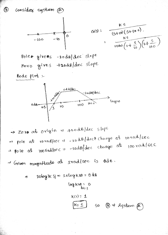
 Consider a causal LTI system implemented as the RL circuit shown below. In this circuit, v(t) is the input voltage. The current i(t) is considered the system output. i(t) R L wwwm v(t) (a) Find the differential equation relating v(t) and i(t). (b) Determine the frequency response of this system (H(jw)). (c) Determine the output it) if v(t) = sin(t), R=10 and L=1. (d) Sketch Bode plot of H (jw) for R=10 and L=1. (e) Determine if the system is...
 Consider a causal LTI S9Stem whch s Characterized by the differente euation a) Determine the transfer Suntion, H(z) os the b) Plot +he pole-Zero diagram for the soh d) Determ ine the impulse response os the o S9stem c) Is the system stable? Tastify your answer e) Find the response os the sostem,uhi,i the
 2.6.1-2.6.62.6.1 Consider a causal contimuous-time LTI system described by the differential equation$$ y^{\prime \prime}(t)+y(t)=x(t) $$(a) Find the transfer function \(H(s)\), its \(R O C\), and its poles.(b) Find the impulse response \(h(t)\).(c) Classify the system as stable/unstable.(d) Find the step response of the system.2.6.2 Given the impulse response of a continuous-time LTI system, find the transfer function \(H(s),\) the \(\mathrm{ROC}\) of \(H(s)\), and the poles of the system. Also find the differential equation describing each system.(a) \(h(t)=\sin (3 t) u(t)\)(b)...
 5. Consider an LTI system with transfer function H(s). Pole-zero plot of H(s) is shown below. Im (a) How many ROCs can be considered for this system? (b) Assume system is causal. Find ROC of H(S) (c) Assume y(t) is system output with step unit as input. Given lim y(t) = 5 , 00 Find H(s).
 3. Consider an LTI system with transfer function H(s). Pole-zero plot of H(s) is shown below. Im O--- Re (a) How many ROCs can be considered for this system? (b) Assume system is causal. Find ROC of H(S) (c) Assume y(t) is system output with step unit as input. Given lim yết) = 5 , Find H(s). (d) (optional) Find y(2) (y(t) for t = 2).
 4. 1 20 points). Consider a causal LTI system with a pole-zero plot for th the dfee equation H(2) as show below. The system is known to have a DC gain of 1. Find the difference equation for this system. Show all work. Z - plane 0.5 -0.5 0.5e
4. 1 20 points). Consider a causal LTI system with a pole-zero plot for th the dfee equation H(2) as show below. The system is known to have a DC gain...
4. 1 20 points). Consider a causal LTI system with a pole-zero plot for th the dfee equation H(2) as show below. The system is known to have a DC gain of 1. Find the difference equation for this system. Show all work. Z - plane 0.5 -0.5 0.5e
4. 1 20 points). Consider a causal LTI system with a pole-zero plot for th the dfee equation H(2) as show below. The system is known to have a DC gain...
 1. A causal LTI system is implemented by the difference equation y(n) = 2r(n) - 0.5 y(n-1). (a) Find the frequency response H/(w) of the system. (b) Plot the pole-zero diagram of the system. Based on the pole zero diagram, roughly sketch the frequency response magnitude |H'(w). (c) Indicate on your sketch of H w , its exact values at w=0, 0.5, and . (d) Find the output signal y(n) produced by the input signal (n) = 3 + cos(0.5...
 Problem 3. The input and the output of a stable and causal LTI system are related by the differential equation dy ) + 64x2 + 8y(t) = 2x(t) dt2 dt i) Find the frequency response of the system H(jw) [2 marks] ii) Using your result in (i) find the impulse response of the system h(t). [3 marks] iii) Find the transfer function of the system H(s), i.e. the Laplace transform of the impulse response [2 marks] iv) Sketch the pole-zero...
 Consider a causal LTI system implemented as the RL circuit shown below. In this circuit, v(t) is the input voltage. The current i(t) is considered the system output. i(t) R L wwwm v(t) (a) Find the differential equation relating v(t) and i(t). (b) Determine the frequency response of this system (H(jw)). (c) Determine the output it) if v(t) = sin(t), R=10 and L=1. (d) Sketch Bode plot of H (jw) for R=10 and L=1. (e) Determine if the system is...
Most questions answered within 3 hours.
-
1. What is a “Bankster”? What is insider trading? Why is it
illegal?
2. What is...
asked 49 seconds from now -
Given:
Curent Assets: $600,000
Total Assets: $2,600,000
Current Liabilities: $500,000
Total Liabilities: $1,700,000
What is the...
asked 1 minute ago -
A transverse wave on a cord is given by
D(x,t)=0.18sin(2.7x−61.0t), where Dand x are in m...
asked 5 minutes ago -
ASSIGNMENT
ANSWER ANY TWO OF THE FOLLOWING IN 2-3 PARAGRAPHS OF EACH
QUESTION.
1: Where is...
asked 4 minutes ago -
Question 1 (5 marks)
Studies have shown that the price elasticity for GP
consultations is -0.2...
asked 6 minutes ago -
The owner of 22 restaurants was asked how he does marketing
research. He answered that he...
asked 10 minutes ago -
The premium on a June 17 British pound call option with a strike
price of $1.2560...
asked 26 minutes ago -
We sometimes have to choose between the highest NPV and IRR;
will we not always get...
asked 21 minutes ago -
How do ethical issues affect decision making and what ethical
issues do you see in the...
asked 23 minutes ago -
Calculate the moment
of inertia (in kg·m2) of a skater given the following
information.
(a)
The...
asked 39 minutes ago -
A small body of mass m performs small oscillations sliding (no
rolling) along the bottom of...
asked 43 minutes ago -
The electric field in the region between two oppositely charged,
parallel, conducting plates has a magnitude...
asked 42 minutes ago