
Homework Answers


Add Answer to:
b) Design a PID controller via root-locus to satisfy the following requirements for the controlled system...
Design Project #1 : Design of PID Controller Design a PID controller so that the step...
 Design Project #1 : Design of PID Controller Design a PID controller so that the step response of the following closed-loop system satisfy (settling time) 3sec, POS(% overshoot) 20%, and steady state tracking error (ess)<0. R(s) Y(s) K, ss +1 If you can reduce both settling time and overshoot, then it would be much better. To verify your answer, you should use Matlab simulink and show that your answer is correct in your report. Describe the detailed design procedure (as...
% We can couple the design of gain on the root locus with a % step-response...
 % We can couple the design of gain on the root locus with a
% step-response simulation for the gain selected. We introduce
the command
% rlocus(G,K), which allows us to specify the range of gain, K,
for plotting the root
% locus. This command will help us smooth the usual root locus
plot by equivalently
% specifying more points via the argument, K. Notice that the
first root locus
% plotted without the argument K is not smooth. We...
% We can couple the design of gain on the root locus with a
% step-response simulation for the gain selected. We introduce
the command
% rlocus(G,K), which allows us to specify the range of gain, K,
for plotting the root
% locus. This command will help us smooth the usual root locus
plot by equivalently
% specifying more points via the argument, K. Notice that the
first root locus
% plotted without the argument K is not smooth. We...
[7] Sketch the root locus for the unity feedback system whose open loop transfer function is K G(s) Draw the root lo...
 [7] Sketch the root locus for the unity feedback system whose open loop transfer function is K G(s) Draw the root locus of the system with the gain Kas a variable. s(s+4) (s2+4s+20) Determine asymptotes, centroid, breakaway point, angle of departure, and the gain at which root locus crosses ja-axis. A control system with type-0 process and a PID controller is shown below. Design the [8 parameters of the PID controller so that the following specifications are satisfied. =100 a)...
Design a phase lead controller using the Root Locus Method for the system described by G(s)....
Design a phase lead controller using the Root Locus Method for the system described by G(s). Ensure that there is a reduction of MORE than 40% of the original settling time, additionally, enure that an overshoot of 12% is not exceeded. G(s)=1/(s3+13s2+32s+20)
Matlab 2. A PID controller allows one to adjust the performance of a plant to the...
 Matlab
2. A PID controller allows one to adjust the performance of a plant to the designer's specifications. The following system is given (s+1)(0.2 s+ 1 )(0.04 s + 1 )(0.00%+1) Create this system symbolically in Matlab. Use the command expand to get it in the form of a ratio of polynomials. Use the coefficients to create a transfer function. Import the transfer function to 'pidTuner. There is no perfect controller. So, to achieve the best result, one has to...
Matlab
2. A PID controller allows one to adjust the performance of a plant to the designer's specifications. The following system is given (s+1)(0.2 s+ 1 )(0.04 s + 1 )(0.00%+1) Create this system symbolically in Matlab. Use the command expand to get it in the form of a ratio of polynomials. Use the coefficients to create a transfer function. Import the transfer function to 'pidTuner. There is no perfect controller. So, to achieve the best result, one has to...
I required to design a PID controller that has overshoot less than 10% with minimise rise...
 I required to design a PID controller that has overshoot less
than 10% with minimise rise time, settling time, peak time and
steady-state error.
The transfer function of the plant is shown below:
and the step response of the open loop system by using unit-step
is shown below:
Then I have designed my PID controller by referring to the
example from Modern Control Engineering 5th Edition by Katsuhiko
Ogata page 572 by using Ziegler Nichols 2nd Method.
I get Kcr...
I required to design a PID controller that has overshoot less
than 10% with minimise rise time, settling time, peak time and
steady-state error.
The transfer function of the plant is shown below:
and the step response of the open loop system by using unit-step
is shown below:
Then I have designed my PID controller by referring to the
example from Modern Control Engineering 5th Edition by Katsuhiko
Ogata page 572 by using Ziegler Nichols 2nd Method.
I get Kcr...
Recall the disc drive problem from Tutorials, where we demonstrated that the system can be written as e(s)+ 1000 Ge...
 Recall the disc drive problem from Tutorials, where we demonstrated that the system can be written as e(s)+ 1000 Ge(s) s(s2 110s 1250) Figure 2: Disc Drive System Block Diagram We will now try to design a compensator with the requirements that i. Overshoot 1096 ii. Ts S 100ms ii. eramp() s 0.001 Do the following (you may use MATLAB at your leisure, but be sure to explain your logic for your design choices) a) Use MATLAB to draw the...
P.2 Design a PID (or a Pl only) for the following unity feedback system as shown...
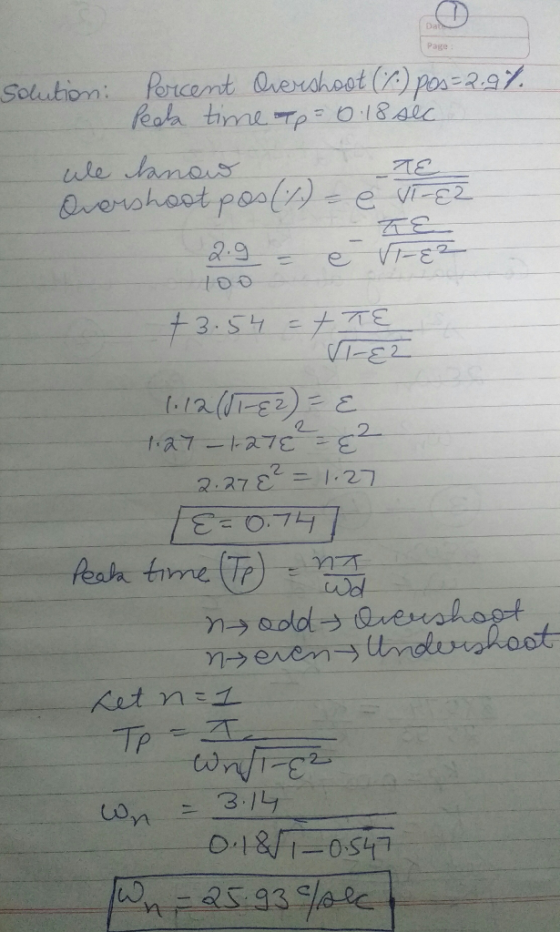
 P.2 Design a PID (or a Pl only) for the following unity feedback system as shown in the figure, where G(s) = (5+1)(s+4) K EG) G The PID (or Pl only), needs to meet the following requirements: a) Tp < 1.047 b) Mp < 1.5% Hint: If designing a PID start now by designing the Pl with the pole and zero close to the origin and then the PD using the all the system's poles and zeros including the Pl.
these are useful formjlas to solve this problem please show all work! thank you 2.) Design...
 these are useful formjlas to solve this problem
please show all work! thank you
2.) Design compensator for zero steady-state error with 10% overshoot and 0.4s of Peak time for the open loop transfer function G specified below. Sketch the comparison between uncompensated and compensated responses. Also compare their root locus. Clearly mention the improvements achieved after compensation. (50 points = 10 pts for analyzing uncompensated system+5 pts for identifying controller type+25 pts for controller design+5 pts for response comparison+5...
these are useful formjlas to solve this problem
please show all work! thank you
2.) Design compensator for zero steady-state error with 10% overshoot and 0.4s of Peak time for the open loop transfer function G specified below. Sketch the comparison between uncompensated and compensated responses. Also compare their root locus. Clearly mention the improvements achieved after compensation. (50 points = 10 pts for analyzing uncompensated system+5 pts for identifying controller type+25 pts for controller design+5 pts for response comparison+5...
i am needing help with a b c o chris question thanks 1000 O(s) Gc(s) s(s2 110s 1250) Figure 2: Disc Drive System Block D...
 i am needing help with a b c o chris question thanks
1000 O(s) Gc(s) s(s2 110s 1250) Figure 2: Disc Drive System Block Diagram We will now try to design a compensator with the requirements that Overshoot 10% ii. Ts S 100ms II. eramp(oo) s 0.001 Do the following (you may use MATLAB at your leisure, but be sure to explain your logic for your design choices) a) Use MATLAB to draw the root locus when Gc K. Augment...
i am needing help with a b c o chris question thanks
1000 O(s) Gc(s) s(s2 110s 1250) Figure 2: Disc Drive System Block Diagram We will now try to design a compensator with the requirements that Overshoot 10% ii. Ts S 100ms II. eramp(oo) s 0.001 Do the following (you may use MATLAB at your leisure, but be sure to explain your logic for your design choices) a) Use MATLAB to draw the root locus when Gc K. Augment...
 Design Project #1 : Design of PID Controller Design a PID controller so that the step response of the following closed-loop system satisfy (settling time) 3sec, POS(% overshoot) 20%, and steady state tracking error (ess)<0. R(s) Y(s) K, ss +1 If you can reduce both settling time and overshoot, then it would be much better. To verify your answer, you should use Matlab simulink and show that your answer is correct in your report. Describe the detailed design procedure (as...
 % We can couple the design of gain on the root locus with a
% step-response simulation for the gain selected. We introduce
the command
% rlocus(G,K), which allows us to specify the range of gain, K,
for plotting the root
% locus. This command will help us smooth the usual root locus
plot by equivalently
% specifying more points via the argument, K. Notice that the
first root locus
% plotted without the argument K is not smooth. We...
% We can couple the design of gain on the root locus with a
% step-response simulation for the gain selected. We introduce
the command
% rlocus(G,K), which allows us to specify the range of gain, K,
for plotting the root
% locus. This command will help us smooth the usual root locus
plot by equivalently
% specifying more points via the argument, K. Notice that the
first root locus
% plotted without the argument K is not smooth. We...
 [7] Sketch the root locus for the unity feedback system whose open loop transfer function is K G(s) Draw the root locus of the system with the gain Kas a variable. s(s+4) (s2+4s+20) Determine asymptotes, centroid, breakaway point, angle of departure, and the gain at which root locus crosses ja-axis. A control system with type-0 process and a PID controller is shown below. Design the [8 parameters of the PID controller so that the following specifications are satisfied. =100 a)...
 Matlab
2. A PID controller allows one to adjust the performance of a plant to the designer's specifications. The following system is given (s+1)(0.2 s+ 1 )(0.04 s + 1 )(0.00%+1) Create this system symbolically in Matlab. Use the command expand to get it in the form of a ratio of polynomials. Use the coefficients to create a transfer function. Import the transfer function to 'pidTuner. There is no perfect controller. So, to achieve the best result, one has to...
Matlab
2. A PID controller allows one to adjust the performance of a plant to the designer's specifications. The following system is given (s+1)(0.2 s+ 1 )(0.04 s + 1 )(0.00%+1) Create this system symbolically in Matlab. Use the command expand to get it in the form of a ratio of polynomials. Use the coefficients to create a transfer function. Import the transfer function to 'pidTuner. There is no perfect controller. So, to achieve the best result, one has to...
 I required to design a PID controller that has overshoot less
than 10% with minimise rise time, settling time, peak time and
steady-state error.
The transfer function of the plant is shown below:
and the step response of the open loop system by using unit-step
is shown below:
Then I have designed my PID controller by referring to the
example from Modern Control Engineering 5th Edition by Katsuhiko
Ogata page 572 by using Ziegler Nichols 2nd Method.
I get Kcr...
I required to design a PID controller that has overshoot less
than 10% with minimise rise time, settling time, peak time and
steady-state error.
The transfer function of the plant is shown below:
and the step response of the open loop system by using unit-step
is shown below:
Then I have designed my PID controller by referring to the
example from Modern Control Engineering 5th Edition by Katsuhiko
Ogata page 572 by using Ziegler Nichols 2nd Method.
I get Kcr...
 Recall the disc drive problem from Tutorials, where we demonstrated that the system can be written as e(s)+ 1000 Ge(s) s(s2 110s 1250) Figure 2: Disc Drive System Block Diagram We will now try to design a compensator with the requirements that i. Overshoot 1096 ii. Ts S 100ms ii. eramp() s 0.001 Do the following (you may use MATLAB at your leisure, but be sure to explain your logic for your design choices) a) Use MATLAB to draw the...
 P.2 Design a PID (or a Pl only) for the following unity feedback system as shown in the figure, where G(s) = (5+1)(s+4) K EG) G The PID (or Pl only), needs to meet the following requirements: a) Tp < 1.047 b) Mp < 1.5% Hint: If designing a PID start now by designing the Pl with the pole and zero close to the origin and then the PD using the all the system's poles and zeros including the Pl.
 these are useful formjlas to solve this problem
please show all work! thank you
2.) Design compensator for zero steady-state error with 10% overshoot and 0.4s of Peak time for the open loop transfer function G specified below. Sketch the comparison between uncompensated and compensated responses. Also compare their root locus. Clearly mention the improvements achieved after compensation. (50 points = 10 pts for analyzing uncompensated system+5 pts for identifying controller type+25 pts for controller design+5 pts for response comparison+5...
these are useful formjlas to solve this problem
please show all work! thank you
2.) Design compensator for zero steady-state error with 10% overshoot and 0.4s of Peak time for the open loop transfer function G specified below. Sketch the comparison between uncompensated and compensated responses. Also compare their root locus. Clearly mention the improvements achieved after compensation. (50 points = 10 pts for analyzing uncompensated system+5 pts for identifying controller type+25 pts for controller design+5 pts for response comparison+5...
 i am needing help with a b c o chris question thanks
1000 O(s) Gc(s) s(s2 110s 1250) Figure 2: Disc Drive System Block Diagram We will now try to design a compensator with the requirements that Overshoot 10% ii. Ts S 100ms II. eramp(oo) s 0.001 Do the following (you may use MATLAB at your leisure, but be sure to explain your logic for your design choices) a) Use MATLAB to draw the root locus when Gc K. Augment...
i am needing help with a b c o chris question thanks
1000 O(s) Gc(s) s(s2 110s 1250) Figure 2: Disc Drive System Block Diagram We will now try to design a compensator with the requirements that Overshoot 10% ii. Ts S 100ms II. eramp(oo) s 0.001 Do the following (you may use MATLAB at your leisure, but be sure to explain your logic for your design choices) a) Use MATLAB to draw the root locus when Gc K. Augment...
Most questions answered within 3 hours.
-
(Expected rate of return and risk) Carter Inc. is evaluating a
security. Calculate the investment’s expected...
asked 29 minutes ago -
What specific indicators can point to lack of progress for
African Americans in American society?
asked 1 hour ago -
1-The Electrons in a beam are moving at 2.7×10⁸ m/s in an
electric field of 15000...
asked 1 hour ago -
A gas tank is a vertical cylinder. It has a radius of 1m, a
height of...
asked 2 hours ago -
Accent Software faces the following conditions. All of these
support Accent’s use of a market-penetration pricing...
asked 3 hours ago -
A mathematically inclined friend emails you the following
instructions: "Meet me in the cafeteria the first...
asked 3 hours ago -
A monopoly sells in two countries . The demand curves in the two
countries are p1...
asked 4 hours ago -
A .15kg rubber ball is bounced off a wall. Before hitting the
wall, the ball moves...
asked 4 hours ago -
A manufacturing company preparing to build a new plant is
considering three potential locations for it....
asked 4 hours ago -
B. If compound Y has approximately the same values of solubility
in toluene as compound X,...
asked 5 hours ago -
Oscar Inc. has inventory in Japan valued at 39,051,000 Yen one
year ago. One year ago...
asked 5 hours ago -
If Canada suffered from "fundamental disequilibrium," and its
government choose not to devalue its currency, a...
asked 5 hours ago