Design a phase lead controller using the Root Locus Method for the system described by G(s)....
Design a phase lead controller using the Root Locus Method for the system described by G(s). Ensure that there is a reduction of MORE than 40% of the original settling time, additionally, enure that an overshoot of 12% is not exceeded.
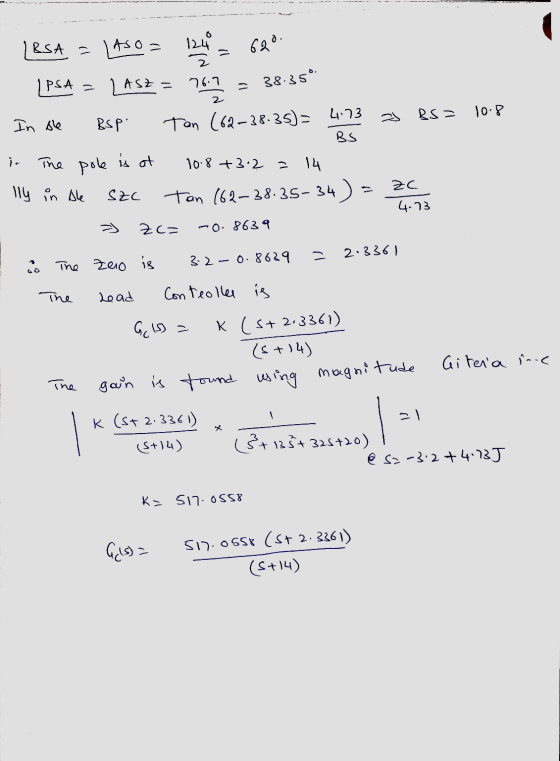
G(s)=1/(s3+13s2+32s+20)
Homework Answers
matlab:
clc;
clear all;
close all;
s=tf('s');
g=1/(s^3+13*s^2+32*s+20);
rlocus(g)


Add Answer to:
Design a phase lead controller using the Root Locus Method for
the system described by G(s)....
Design Problems: (1) A robotic system is described by the transfer function P(s)=- 100 s(s +9.7)(s...
 Design Problems: (1) A robotic system is described by the transfer function P(s)=- 100 s(s +9.7)(s + 51.2) Use the root locus method to design a lead controller that achieves a closed-loop step response with P.0.5 2.5 %, and a settling time T, < 0.25s (using the 2% criterion). Also, the steady-state error to a unit ramp should be ess < 0.15. (2) This system is open-loop unstable: P(S) = 500 (5 - 1)(s + 10) Using the root locus...
Lag Compensator Design Using Root-Locus 2. Consider the unity feedback system in Figure 1 for G(s...
 Lag Compensator Design Using Root-Locus 2. Consider the unity feedback system in Figure 1 for G(s)- s(s+3(s6) Design a lag compensation to meet the following specifications The step response settling time is to be less than 5 sec. . The step response overshoot is to be less than 17% . The steady-state error to a unit ramp input must not exceed 10%. Dynamic specifications (overshoot and settling time) can be met using proportional feedback, but a lag compensator is needed...
b) Design a PID controller via root-locus to satisfy the following requirements for the controlled system...
 b) Design a PID controller via root-locus to satisfy the following requirements for the controlled system 2.9 T,-0.18 The following notation has been used for the system parameters: Percent Overshoot(%)-pos Settling time (s) Peak time (s)- Tp Start by manual calculations for the locations of the poles and zeros of the PID controller to satisfy the requirements. Find the required location of the zero for PD control and introduce PI control. Afterwards, use the Sisotool in MATLAB to simulate the...
3. Lead Comensator Design Using Root-Locus Consider the system in Figure 1 for G(s) -1/s* Design ...
 3. Lead Comensator Design Using Root-Locus Consider the system in Figure 1 for G(s) -1/s* Design a lead compensator D(s)-K (s+ z)/(s+ p) to meet the specifications: tR 0.636 s , MP 5 % . We choose z1. Find K and jp Y(s) R(S) Figure 1. Unity Feedback System
3. Lead Comensator Design Using Root-Locus Consider the system in Figure 1 for G(s) -1/s* Design a lead compensator D(s)-K (s+ z)/(s+ p) to meet the specifications: tR 0.636 s ,...
3. Lead Comensator Design Using Root-Locus Consider the system in Figure 1 for G(s) -1/s* Design a lead compensator D(s)-K (s+ z)/(s+ p) to meet the specifications: tR 0.636 s , MP 5 % . We choose z1. Find K and jp Y(s) R(S) Figure 1. Unity Feedback System
3. Lead Comensator Design Using Root-Locus Consider the system in Figure 1 for G(s) -1/s* Design a lead compensator D(s)-K (s+ z)/(s+ p) to meet the specifications: tR 0.636 s ,...
Design a PD controller for mass-spring systems by the Root-Locus Method Mass 2.6Kg Spring stiffness 200N/m Zero Damp...
 Design a PD controller for mass-spring systems by the Root-Locus Method Mass 2.6Kg Spring stiffness 200N/m Zero Damper Input: force Output: mass displacement, y Design a PD controller, Kp+ Kd*s, for vibration reduction by root-locus method so that the damping ratio of the closed-loop systems is 0.5 and natural frequency is 3 rad/s Transfer Function of closed-loop system Draw root locus plot Design gains ww
Design a PD controller for mass-spring systems by the Root-Locus Method Mass 2.6Kg Spring stiffness...
Design a PD controller for mass-spring systems by the Root-Locus Method Mass 2.6Kg Spring stiffness 200N/m Zero Damper Input: force Output: mass displacement, y Design a PD controller, Kp+ Kd*s, for vibration reduction by root-locus method so that the damping ratio of the closed-loop systems is 0.5 and natural frequency is 3 rad/s Transfer Function of closed-loop system Draw root locus plot Design gains ww
Design a PD controller for mass-spring systems by the Root-Locus Method Mass 2.6Kg Spring stiffness...
A system having an open loop transfer function of G(S) = K10/(S+2)(3+1) has a root locus...
 A system having an open loop transfer function of G(S) = K10/(S+2)(3+1) has a root locus plot as shown below. The location of the roots for a system gain of K= 0.248 is show on the plot. At this location the system has a damping factor of 0.708 and a settling time of 4/1.5 = 2.67 seconds. A lead compensator is to be used to improve the transient response. (Note that nothing is plotted on the graph except for that...
% We can couple the design of gain on the root locus with a % step-response...
 % We can couple the design of gain on the root locus with a
% step-response simulation for the gain selected. We introduce
the command
% rlocus(G,K), which allows us to specify the range of gain, K,
for plotting the root
% locus. This command will help us smooth the usual root locus
plot by equivalently
% specifying more points via the argument, K. Notice that the
first root locus
% plotted without the argument K is not smooth. We...
% We can couple the design of gain on the root locus with a
% step-response simulation for the gain selected. We introduce
the command
% rlocus(G,K), which allows us to specify the range of gain, K,
for plotting the root
% locus. This command will help us smooth the usual root locus
plot by equivalently
% specifying more points via the argument, K. Notice that the
first root locus
% plotted without the argument K is not smooth. We...
Question 1 (60 points) Consider the following block diagram where G(s)- Controller R(s) G(s) (a) Sketch the root locus assuming a proportional controller is used. [25 points] (b) Design specifica...
 Question 1 (60 points) Consider the following block diagram where G(s)- Controller R(s) G(s) (a) Sketch the root locus assuming a proportional controller is used. [25 points] (b) Design specifications require a closed-loop pole at (-3+j1). Design a lead compensator to make sure the root locus goes through this point. For the design, pick the pole of the compensator at-23 and analytically find its zero. (Hint: Lead compensator transfer function will be Ge (s)$+23 First plot the poles and zeros...
3. (28 pts.) The unity feedback system with K(5+3) G(s) = (s + 1)(s + 4)(s...
 3. (28 pts.) The unity feedback system with K(5+3) G(s) = (s + 1)(s + 4)(s + 10) is operating with 12% overshoot ({=0.56). (a) the root locus plot is below, find the settling time (b) find ko (c) using frequency response techniques, design a lead compensator that will yield a twofold improvement in K, and a twofold reduction in settling time while keeping the overshoot at 12%; the Bode plot is below using the margin command and using the...
[7] Sketch the root locus for the unity feedback system whose open loop transfer function is K G(s) Draw the root lo...
 [7] Sketch the root locus for the unity feedback system whose open loop transfer function is K G(s) Draw the root locus of the system with the gain Kas a variable. s(s+4) (s2+4s+20) Determine asymptotes, centroid, breakaway point, angle of departure, and the gain at which root locus crosses ja-axis. A control system with type-0 process and a PID controller is shown below. Design the [8 parameters of the PID controller so that the following specifications are satisfied. =100 a)...
 Design Problems: (1) A robotic system is described by the transfer function P(s)=- 100 s(s +9.7)(s + 51.2) Use the root locus method to design a lead controller that achieves a closed-loop step response with P.0.5 2.5 %, and a settling time T, < 0.25s (using the 2% criterion). Also, the steady-state error to a unit ramp should be ess < 0.15. (2) This system is open-loop unstable: P(S) = 500 (5 - 1)(s + 10) Using the root locus...
 Lag Compensator Design Using Root-Locus 2. Consider the unity feedback system in Figure 1 for G(s)- s(s+3(s6) Design a lag compensation to meet the following specifications The step response settling time is to be less than 5 sec. . The step response overshoot is to be less than 17% . The steady-state error to a unit ramp input must not exceed 10%. Dynamic specifications (overshoot and settling time) can be met using proportional feedback, but a lag compensator is needed...
 b) Design a PID controller via root-locus to satisfy the following requirements for the controlled system 2.9 T,-0.18 The following notation has been used for the system parameters: Percent Overshoot(%)-pos Settling time (s) Peak time (s)- Tp Start by manual calculations for the locations of the poles and zeros of the PID controller to satisfy the requirements. Find the required location of the zero for PD control and introduce PI control. Afterwards, use the Sisotool in MATLAB to simulate the...
 3. Lead Comensator Design Using Root-Locus Consider the system in Figure 1 for G(s) -1/s* Design a lead compensator D(s)-K (s+ z)/(s+ p) to meet the specifications: tR 0.636 s , MP 5 % . We choose z1. Find K and jp Y(s) R(S) Figure 1. Unity Feedback System
3. Lead Comensator Design Using Root-Locus Consider the system in Figure 1 for G(s) -1/s* Design a lead compensator D(s)-K (s+ z)/(s+ p) to meet the specifications: tR 0.636 s ,...
3. Lead Comensator Design Using Root-Locus Consider the system in Figure 1 for G(s) -1/s* Design a lead compensator D(s)-K (s+ z)/(s+ p) to meet the specifications: tR 0.636 s , MP 5 % . We choose z1. Find K and jp Y(s) R(S) Figure 1. Unity Feedback System
3. Lead Comensator Design Using Root-Locus Consider the system in Figure 1 for G(s) -1/s* Design a lead compensator D(s)-K (s+ z)/(s+ p) to meet the specifications: tR 0.636 s ,...
 Design a PD controller for mass-spring systems by the Root-Locus Method Mass 2.6Kg Spring stiffness 200N/m Zero Damper Input: force Output: mass displacement, y Design a PD controller, Kp+ Kd*s, for vibration reduction by root-locus method so that the damping ratio of the closed-loop systems is 0.5 and natural frequency is 3 rad/s Transfer Function of closed-loop system Draw root locus plot Design gains ww
Design a PD controller for mass-spring systems by the Root-Locus Method Mass 2.6Kg Spring stiffness...
Design a PD controller for mass-spring systems by the Root-Locus Method Mass 2.6Kg Spring stiffness 200N/m Zero Damper Input: force Output: mass displacement, y Design a PD controller, Kp+ Kd*s, for vibration reduction by root-locus method so that the damping ratio of the closed-loop systems is 0.5 and natural frequency is 3 rad/s Transfer Function of closed-loop system Draw root locus plot Design gains ww
Design a PD controller for mass-spring systems by the Root-Locus Method Mass 2.6Kg Spring stiffness...
 A system having an open loop transfer function of G(S) = K10/(S+2)(3+1) has a root locus plot as shown below. The location of the roots for a system gain of K= 0.248 is show on the plot. At this location the system has a damping factor of 0.708 and a settling time of 4/1.5 = 2.67 seconds. A lead compensator is to be used to improve the transient response. (Note that nothing is plotted on the graph except for that...
 % We can couple the design of gain on the root locus with a
% step-response simulation for the gain selected. We introduce
the command
% rlocus(G,K), which allows us to specify the range of gain, K,
for plotting the root
% locus. This command will help us smooth the usual root locus
plot by equivalently
% specifying more points via the argument, K. Notice that the
first root locus
% plotted without the argument K is not smooth. We...
% We can couple the design of gain on the root locus with a
% step-response simulation for the gain selected. We introduce
the command
% rlocus(G,K), which allows us to specify the range of gain, K,
for plotting the root
% locus. This command will help us smooth the usual root locus
plot by equivalently
% specifying more points via the argument, K. Notice that the
first root locus
% plotted without the argument K is not smooth. We...
 Question 1 (60 points) Consider the following block diagram where G(s)- Controller R(s) G(s) (a) Sketch the root locus assuming a proportional controller is used. [25 points] (b) Design specifications require a closed-loop pole at (-3+j1). Design a lead compensator to make sure the root locus goes through this point. For the design, pick the pole of the compensator at-23 and analytically find its zero. (Hint: Lead compensator transfer function will be Ge (s)$+23 First plot the poles and zeros...
 3. (28 pts.) The unity feedback system with K(5+3) G(s) = (s + 1)(s + 4)(s + 10) is operating with 12% overshoot ({=0.56). (a) the root locus plot is below, find the settling time (b) find ko (c) using frequency response techniques, design a lead compensator that will yield a twofold improvement in K, and a twofold reduction in settling time while keeping the overshoot at 12%; the Bode plot is below using the margin command and using the...
 [7] Sketch the root locus for the unity feedback system whose open loop transfer function is K G(s) Draw the root locus of the system with the gain Kas a variable. s(s+4) (s2+4s+20) Determine asymptotes, centroid, breakaway point, angle of departure, and the gain at which root locus crosses ja-axis. A control system with type-0 process and a PID controller is shown below. Design the [8 parameters of the PID controller so that the following specifications are satisfied. =100 a)...
Most questions answered within 3 hours.
-
Imagine that a chemist puts 6.40 mol each of
C3H8 and O2 in a 1.00-L container...
asked 7 minutes ago -
How much money should be invested today in order to have $8340
at the end of...
asked 11 minutes ago -
You are conducting research for a hospital and issue a survey to
patients.
Based on the...
asked 11 minutes ago -
What might be a negative mutation that would hinder the
bug population?
asked 21 minutes ago -
A company just paid a dividend of $1.50 per share. The consensus
forecast of financial analysts...
asked 16 minutes ago -
A mass of 0.50 g of an unknown acid HA required 20.0 mL of 0.25
M...
asked 26 minutes ago -
Mitch is a director and officer of Numero Uno, Inc. Mitch makes
a marketing decision that...
asked 27 minutes ago -
A pair of fair dice is tossed. Let X denote the larger of the
two numbers...
asked 35 minutes ago -
What are the variety of forms of products dispensed with aerosol
spray?
asked 39 minutes ago -
Which one of the following statements is true about C++
keywords?
a. A keyword can have...
asked 40 minutes ago -
Pyruvate Kinase, an allosteric enzyme, accelerates the
conversion of phosphoenolpyruvate to pyruvate.
1) Draw curves describing...
asked 42 minutes ago -
question 1
Which of the following is an example of a bottom-up technique
for developing promotional...
asked 59 minutes ago