

Y(s) R(S) Figure 1. Unity Feedback System
Homework Answers

Add Answer to:
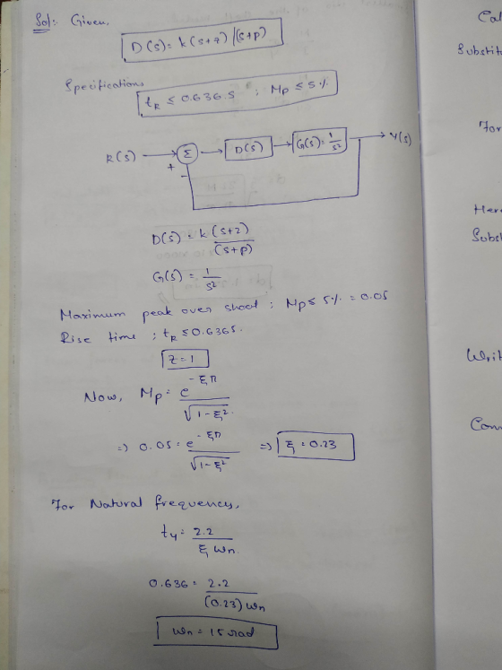
3. Lead Comensator Design Using Root-Locus Consider the system in Figure 1 for G(s) -1/s* Design ...
Lag Compensator Design Using Root-Locus 2. Consider the unity feedback system in Figure 1 for G(s...
 Lag Compensator Design Using Root-Locus 2. Consider the unity feedback system in Figure 1 for G(s)- s(s+3(s6) Design a lag compensation to meet the following specifications The step response settling time is to be less than 5 sec. . The step response overshoot is to be less than 17% . The steady-state error to a unit ramp input must not exceed 10%. Dynamic specifications (overshoot and settling time) can be met using proportional feedback, but a lag compensator is needed...
Q1. Show analytically that the Root Locus for the unity feedback system with open loop transfer f...
 Q1. Show analytically that the Root Locus for the unity feedback system with open loop transfer function: (a) [10 marks] K(s 4) (s + 2) is a circle, and find the centre and the radius. Determine the minimum value of the damping ratio and the corresponding value of K (b) The root locus of the open loop transfer function: [10 marks] s(s26s +15) is depicted in Figure Q1(b). Find the minimum value of gain K that will render the system...
[7] Sketch the root locus for the unity feedback system whose open loop transfer function is K G(s) Draw the root lo...
 [7] Sketch the root locus for the unity feedback system whose open loop transfer function is K G(s) Draw the root locus of the system with the gain Kas a variable. s(s+4) (s2+4s+20) Determine asymptotes, centroid, breakaway point, angle of departure, and the gain at which root locus crosses ja-axis. A control system with type-0 process and a PID controller is shown below. Design the [8 parameters of the PID controller so that the following specifications are satisfied. =100 a)...
Question 1 (60 points) Consider the following block diagram where G(s)- Controller R(s) G(s) (a) Sketch the root locus assuming a proportional controller is used. [25 points] (b) Design specifica...
 Question 1 (60 points) Consider the following block diagram where G(s)- Controller R(s) G(s) (a) Sketch the root locus assuming a proportional controller is used. [25 points] (b) Design specifications require a closed-loop pole at (-3+j1). Design a lead compensator to make sure the root locus goes through this point. For the design, pick the pole of the compensator at-23 and analytically find its zero. (Hint: Lead compensator transfer function will be Ge (s)$+23 First plot the poles and zeros...
design this compensator using root locus? note: answer using root locus 1- Consider a system with the following...
 design this compensator using root locus?
note: answer using root locus
1- Consider a system with the following open loop Transfer Function: G(s)--10 s(s2 + 10s + 16) Design a compensator to obtain a damping ratio-0.5 and a natural frequency n6 rad/sec. (8 marks) We were unable to transcribe this image
1- Consider a system with the following open loop Transfer Function: G(s)--10 s(s2 + 10s + 16) Design a compensator to obtain a damping ratio-0.5 and a natural frequency...
design this compensator using root locus?
note: answer using root locus
1- Consider a system with the following open loop Transfer Function: G(s)--10 s(s2 + 10s + 16) Design a compensator to obtain a damping ratio-0.5 and a natural frequency n6 rad/sec. (8 marks) We were unable to transcribe this image
1- Consider a system with the following open loop Transfer Function: G(s)--10 s(s2 + 10s + 16) Design a compensator to obtain a damping ratio-0.5 and a natural frequency...
4) 3s points 11. Given the unity feedback system of Figure P9.1 with G(s) K (s + 6) do the following: [Section: 9.3 a. Sketch the root locus. b) Using the operating point of -3.2+j2.38 find the g...
 4) 3s points 11. Given the unity feedback system of Figure P9.1 with G(s) K (s + 6) do the following: [Section: 9.3 a. Sketch the root locus. b) Using the operating point of -3.2+j2.38 find the gain K. c) if the system is to be cascade-compensated so that T, -1 sec, find the compensator compensator zero is at -45. pole if the d) Sketch the root locus for the new compensated system.
4) 3s points 11. Given the unity...
4) 3s points 11. Given the unity feedback system of Figure P9.1 with G(s) K (s + 6) do the following: [Section: 9.3 a. Sketch the root locus. b) Using the operating point of -3.2+j2.38 find the gain K. c) if the system is to be cascade-compensated so that T, -1 sec, find the compensator compensator zero is at -45. pole if the d) Sketch the root locus for the new compensated system.
4) 3s points 11. Given the unity...
Problem 4. The open-loop transfer function of a unity feedback system is 20 G(s) S+1.5) (s +3.5) ...
 Problem 4. The open-loop transfer function of a unity feedback system is 20 G(s) S+1.5) (s +3.5) (s +15) (a) Design a lag-lead compensator for G(s) using root locus so that the closed-loop system satisfies the design specifications. (b) Design a PID compensator for G(s) using root locus so that the closed-loop system satisfies the design specifications. Design specifications -SSE to a unit step reference input is less than 0.02. Overshoot is less than 20%. Peak time is less than...
A plant with the transfer function Gp(s)-- with unity feedback has the root locus shown in the figure below: (s+2)(s+4) Root Locus 1.5 C(s) 0.5 0.5 1.5 .3 Real Axis (seconds) (a) Determine K of G...
 A plant with the transfer function Gp(s)-- with unity feedback has the root locus shown in the figure below: (s+2)(s+4) Root Locus 1.5 C(s) 0.5 0.5 1.5 .3 Real Axis (seconds) (a) Determine K of Gp(s) if it is desired that the uncompensated system has a 10% OS (overshoot) to a step input. (4 points) a 5% overshoot and a peak time Tp 3.1 meets the requirements described in part (b) and achieves zero steady state (b) Compute the desired...
Problem 4. The open-loop transfer function of a unity feedback system is: 20 (s+1.5)(s 3.5) (s 15...
 Problem 4. The open-loop transfer function of a unity feedback system is: 20 (s+1.5)(s 3.5) (s 15) G(s) (a) Design a lag-lead compensator for G(s) using root locus so that the closed-loop system satisfies the design specifications (b) Design a PID compensator for G (s) using root locus so that the clos ed-loop system satisfies the design specifications. Design specifications .SSE to a unit step reference input is less than 0.02. Overshoot is less than 20% Peak time is less...
1. Using the MATLAB rltool command (or rlocus and rlocfind), plot the K > 0 root...
 1. Using the MATLAB rltool command (or rlocus and rlocfind), plot the K > 0 root locus for What is the value of the largest damping ra- 2+2s+1 s(s120)7,7 -2,12). 1 + KL(s) = 0, where L(s) = tio associated with the pair of complex poles? At which value of K is it achieved? Turn in a printout of your plot showing the location of the poles on the damping ratio line that you found. 2. Suppose the unity feedback...
 Lag Compensator Design Using Root-Locus 2. Consider the unity feedback system in Figure 1 for G(s)- s(s+3(s6) Design a lag compensation to meet the following specifications The step response settling time is to be less than 5 sec. . The step response overshoot is to be less than 17% . The steady-state error to a unit ramp input must not exceed 10%. Dynamic specifications (overshoot and settling time) can be met using proportional feedback, but a lag compensator is needed...
 Q1. Show analytically that the Root Locus for the unity feedback system with open loop transfer function: (a) [10 marks] K(s 4) (s + 2) is a circle, and find the centre and the radius. Determine the minimum value of the damping ratio and the corresponding value of K (b) The root locus of the open loop transfer function: [10 marks] s(s26s +15) is depicted in Figure Q1(b). Find the minimum value of gain K that will render the system...
 [7] Sketch the root locus for the unity feedback system whose open loop transfer function is K G(s) Draw the root locus of the system with the gain Kas a variable. s(s+4) (s2+4s+20) Determine asymptotes, centroid, breakaway point, angle of departure, and the gain at which root locus crosses ja-axis. A control system with type-0 process and a PID controller is shown below. Design the [8 parameters of the PID controller so that the following specifications are satisfied. =100 a)...
 Question 1 (60 points) Consider the following block diagram where G(s)- Controller R(s) G(s) (a) Sketch the root locus assuming a proportional controller is used. [25 points] (b) Design specifications require a closed-loop pole at (-3+j1). Design a lead compensator to make sure the root locus goes through this point. For the design, pick the pole of the compensator at-23 and analytically find its zero. (Hint: Lead compensator transfer function will be Ge (s)$+23 First plot the poles and zeros...
 design this compensator using root locus?
note: answer using root locus
1- Consider a system with the following open loop Transfer Function: G(s)--10 s(s2 + 10s + 16) Design a compensator to obtain a damping ratio-0.5 and a natural frequency n6 rad/sec. (8 marks) We were unable to transcribe this image
1- Consider a system with the following open loop Transfer Function: G(s)--10 s(s2 + 10s + 16) Design a compensator to obtain a damping ratio-0.5 and a natural frequency...
design this compensator using root locus?
note: answer using root locus
1- Consider a system with the following open loop Transfer Function: G(s)--10 s(s2 + 10s + 16) Design a compensator to obtain a damping ratio-0.5 and a natural frequency n6 rad/sec. (8 marks) We were unable to transcribe this image
1- Consider a system with the following open loop Transfer Function: G(s)--10 s(s2 + 10s + 16) Design a compensator to obtain a damping ratio-0.5 and a natural frequency...
 4) 3s points 11. Given the unity feedback system of Figure P9.1 with G(s) K (s + 6) do the following: [Section: 9.3 a. Sketch the root locus. b) Using the operating point of -3.2+j2.38 find the gain K. c) if the system is to be cascade-compensated so that T, -1 sec, find the compensator compensator zero is at -45. pole if the d) Sketch the root locus for the new compensated system.
4) 3s points 11. Given the unity...
4) 3s points 11. Given the unity feedback system of Figure P9.1 with G(s) K (s + 6) do the following: [Section: 9.3 a. Sketch the root locus. b) Using the operating point of -3.2+j2.38 find the gain K. c) if the system is to be cascade-compensated so that T, -1 sec, find the compensator compensator zero is at -45. pole if the d) Sketch the root locus for the new compensated system.
4) 3s points 11. Given the unity...
 Problem 4. The open-loop transfer function of a unity feedback system is 20 G(s) S+1.5) (s +3.5) (s +15) (a) Design a lag-lead compensator for G(s) using root locus so that the closed-loop system satisfies the design specifications. (b) Design a PID compensator for G(s) using root locus so that the closed-loop system satisfies the design specifications. Design specifications -SSE to a unit step reference input is less than 0.02. Overshoot is less than 20%. Peak time is less than...
 A plant with the transfer function Gp(s)-- with unity feedback has the root locus shown in the figure below: (s+2)(s+4) Root Locus 1.5 C(s) 0.5 0.5 1.5 .3 Real Axis (seconds) (a) Determine K of Gp(s) if it is desired that the uncompensated system has a 10% OS (overshoot) to a step input. (4 points) a 5% overshoot and a peak time Tp 3.1 meets the requirements described in part (b) and achieves zero steady state (b) Compute the desired...
 Problem 4. The open-loop transfer function of a unity feedback system is: 20 (s+1.5)(s 3.5) (s 15) G(s) (a) Design a lag-lead compensator for G(s) using root locus so that the closed-loop system satisfies the design specifications (b) Design a PID compensator for G (s) using root locus so that the clos ed-loop system satisfies the design specifications. Design specifications .SSE to a unit step reference input is less than 0.02. Overshoot is less than 20% Peak time is less...
 1. Using the MATLAB rltool command (or rlocus and rlocfind), plot the K > 0 root locus for What is the value of the largest damping ra- 2+2s+1 s(s120)7,7 -2,12). 1 + KL(s) = 0, where L(s) = tio associated with the pair of complex poles? At which value of K is it achieved? Turn in a printout of your plot showing the location of the poles on the damping ratio line that you found. 2. Suppose the unity feedback...
Most questions answered within 3 hours.
-
At a local university, you poll a group of 115 students and find
that 37 of...
asked 2 minutes from now -
Gladstone company tracks the number of units purchased and sold
throughout each accounting period but applies...
asked 1 minute ago -
When determining if a molecule's configuration is E or Z, what
determines the higher priority groups?
asked 5 minutes ago -
13. What is the amount
of conversion cost transferred to finished goods? (Round
your intermediate calculations...
asked 6 minutes ago -
Sulfuric Acid is a "strong" acid, but only releases a single
proton when it dissolves. What...
asked 6 minutes ago -
The
second floor of a house is 6 m above the street level. How much
work...
asked 8 minutes ago -
What uncontrollable factor(s) contributed to Hong Kong Disney’s
poor performance during its first year?
asked 10 minutes ago -
I wish to estimate µ, the mean of a population. After I collect
and an-
alyze...
asked 16 minutes ago -
You are interested in whether students that have a male
instructors perform differently on exams. To...
asked 22 minutes ago -
Discuss the following: The policies that promote economic
growth. Why are some countries more developed than...
asked 18 minutes ago -
I am supposed to reduce redundancy in the code and also make
unknown inputs, output "unknown"....
asked 24 minutes ago -
The ages of a group of
147
randomly selected adult females have a standard deviation of...
asked 28 minutes ago