gm = 1.6 mS, r(pi)= 62.5 kOhm, ro= 1.875 MOhm, Rin= 39.2 kOhm, Rout= 37.6 kOhm, Av = -59, Av with RE added = -14.6, RiB with RE added = 264.5 kOhm

Homework Answers


Add Answer to:
gm = 1.6 mS, r(pi)= 62.5 kOhm, ro= 1.875 MOhm, Rin= 39.2 kOhm,
Rout= 37.6 kOhm,...
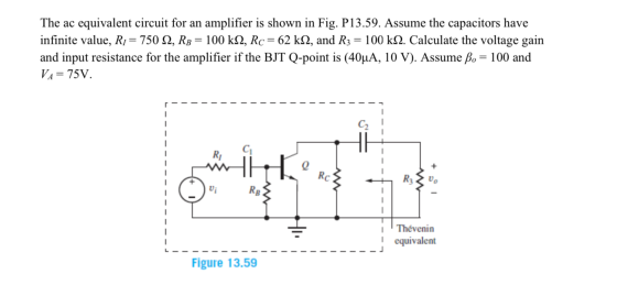
All questions refer to textbook problem 13.59. For questions 7-11, a 2 kq unbypassed Re is...
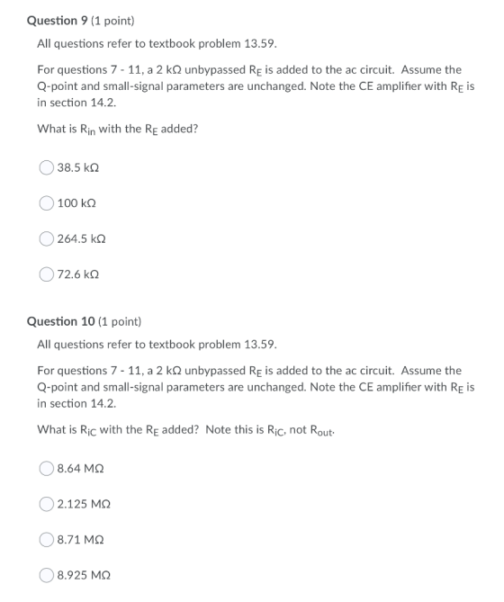
 All questions refer to textbook problem 13.59. For questions 7-11, a 2 kq unbypassed Re is added to the ac circuit. Assume the Q-point and small-signal parameters are unchanged. Note the CE amplifier with Reis in section 14.2 What is Rin with the Rę added? 72.6 k 2 38.5 ko 100k 264.5 k 2 Question 10 (1 point) All questions refer to textbook problem 13.59. For questions 7-11, a 2 kq unbypassed Rę is added to the ac circuit. Assume...
answer all R; " Problem 2) What are the values of Rin, Rout, Ay, and A,...
 answer all
R; " Problem 2) What are the values of Rin, Rout, Ay, and A, for the amplifier given if R = 5000, R3 = 1MA, RE = 120k2, Rc = 56k2, R3 = 500kn, Vcc = 15V, -Vee = -15V? Assume Q-point of the transistor is known as (0.109mA, 12.2V). Use B. = 100 and assume VA = 00. (a) Find the small-signal parameters (9m, Pero). (b) Draw the small-signal model for the circuit." (c) Compute Rin, Rout,...
answer all
R; " Problem 2) What are the values of Rin, Rout, Ay, and A, for the amplifier given if R = 5000, R3 = 1MA, RE = 120k2, Rc = 56k2, R3 = 500kn, Vcc = 15V, -Vee = -15V? Assume Q-point of the transistor is known as (0.109mA, 12.2V). Use B. = 100 and assume VA = 00. (a) Find the small-signal parameters (9m, Pero). (b) Draw the small-signal model for the circuit." (c) Compute Rin, Rout,...
5. (20 points) For the amplifier in the following figure: +Vcc Rout Rc C3 R2 Rin Ri 1 k R3 Vo Vi R1 RE -VEE a) Draw the de equivalent circuit and find the Q-point. Assume B -75 b) Draw the equiv...
 5. (20 points) For the amplifier in the following figure: +Vcc Rout Rc C3 R2 Rin Ri 1 k R3 Vo Vi R1 RE -VEE a) Draw the de equivalent circuit and find the Q-point. Assume B -75 b) Draw the equivalent circuit used for ac analysis. Find the values in Thevenin equivalent representation for the amplifiers between C, and C as shown below. What is the maximum value of v, that satisfies the small- signal assumption? Rout Ri vi...
Voc Ri Rc C2 + RS G Q2N3904 RL Vout 2 R2 RE CE Rin Rout...
 Voc Ri Rc C2 + RS G Q2N3904 RL Vout 2 R2 RE CE Rin Rout Cu B 1x B C o + V be : Cr 8m'be E VCC R R2 Rc RE RS RL С. Cz CE 12 V 8.2 kg 3.9 ko 6.3 k2 3.3 kΩ 3 ko 3.9 ko 10 uF 1uF 100 u Assume the 2N3904 has a 8 =100, Veron} = 0.7V, VA= 100V, C=100, C=13.9pF and Ce=8pF. Use the emission coefficient as n...
4. For the amplifier in the figure below use the parameters in the table: +Vcc Re VBE- 0.7V, Ri- ...
 4. For the amplifier in the figure below use the parameters in the table: +Vcc Re VBE- 0.7V, Ri- 1002, R1-160k2, R2-320k2 R3-200k2, R6-40 k2, Rc-60k2, Vcc- 12V, Ry Do a) Draw the DC equivalent circuit and calculate the Q-point. c) Draw the AC equivalent circuit with the small signal model for the transistor. d) Calculate the voltage gain, Av-Vo/vi. Assume ro infinite. e) Draw the circuit to find the amplifier input resistance (Rin). Calculate Rin f Draw the circuit...
A common source amplifier circuit based on a single n-channel MOSFET is shown in Figure 4b. Assume that the transconductance gm-60 mS (equivalent to mA/ V) and drain source resistance, os,...
 A common source amplifier circuit based on a single n-channel MOSFET is shown in Figure 4b. Assume that the transconductance gm-60 mS (equivalent to mA/ V) and drain source resistance, os, is so large it may be neglected. 0) Calculate the open circuit voltage gain Av Yout/ Vis. i) The amplifier has a load of 10 k2. Determine the current gain Va. = 12 V 150k 4k3 Vout Vin 200k GND = 0 V Figure 4b a) State the name...
Electronics1. It's a multiple choices question. use the formula sheet if needed (the last picture). Question...
 Electronics1. It's a multiple choices question. use the formula
sheet if needed (the last picture).
Question 9 CIRCUIT X/FIG.9 (5 Marks) Statement: Consider the RC-coupled amplifier circuit illustrated in Fig. 9 (CIRCUIT X). Sketching relevant output (V-I) characteristics that decide Q-point coordinates and DC load-line details of the NPN-BJT/Si circuit of Fig. 9 of Circuit x) Further, establish an appropriate AC-load line and decide the maximum swing of the output voltage across Road with respect to the Q-point. Assume the...
Electronics1. It's a multiple choices question. use the formula
sheet if needed (the last picture).
Question 9 CIRCUIT X/FIG.9 (5 Marks) Statement: Consider the RC-coupled amplifier circuit illustrated in Fig. 9 (CIRCUIT X). Sketching relevant output (V-I) characteristics that decide Q-point coordinates and DC load-line details of the NPN-BJT/Si circuit of Fig. 9 of Circuit x) Further, establish an appropriate AC-load line and decide the maximum swing of the output voltage across Road with respect to the Q-point. Assume the...
Electronics1. It's a multiple choices question. use the formula sheet if needed (the last picture). Question:...
 Electronics1. It's a multiple choices question. use the
formula sheet if needed (the last picture).
Question: 10 CIRCUIT Y/FIG.10 (5 Marks) Statement: Consider the RC-coupled amplifier circuit illustrated in Fig. 10 (CIRCUIT Y). Sketching relevant output (Vc-le) characteristics, decide Q-point coordinates and DC load-line details of the NPN-BJT/Si circuit of Fig.10 of Circuit Y). Further, establish an appropriate AC-load line and decide the maximum swing of the output voltage across Road with respect to the Q-point. Assume the input signal...
Electronics1. It's a multiple choices question. use the
formula sheet if needed (the last picture).
Question: 10 CIRCUIT Y/FIG.10 (5 Marks) Statement: Consider the RC-coupled amplifier circuit illustrated in Fig. 10 (CIRCUIT Y). Sketching relevant output (Vc-le) characteristics, decide Q-point coordinates and DC load-line details of the NPN-BJT/Si circuit of Fig.10 of Circuit Y). Further, establish an appropriate AC-load line and decide the maximum swing of the output voltage across Road with respect to the Q-point. Assume the input signal...
 All questions refer to textbook problem 13.59. For questions 7-11, a 2 kq unbypassed Re is added to the ac circuit. Assume the Q-point and small-signal parameters are unchanged. Note the CE amplifier with Reis in section 14.2 What is Rin with the Rę added? 72.6 k 2 38.5 ko 100k 264.5 k 2 Question 10 (1 point) All questions refer to textbook problem 13.59. For questions 7-11, a 2 kq unbypassed Rę is added to the ac circuit. Assume...
 answer all
R; " Problem 2) What are the values of Rin, Rout, Ay, and A, for the amplifier given if R = 5000, R3 = 1MA, RE = 120k2, Rc = 56k2, R3 = 500kn, Vcc = 15V, -Vee = -15V? Assume Q-point of the transistor is known as (0.109mA, 12.2V). Use B. = 100 and assume VA = 00. (a) Find the small-signal parameters (9m, Pero). (b) Draw the small-signal model for the circuit." (c) Compute Rin, Rout,...
answer all
R; " Problem 2) What are the values of Rin, Rout, Ay, and A, for the amplifier given if R = 5000, R3 = 1MA, RE = 120k2, Rc = 56k2, R3 = 500kn, Vcc = 15V, -Vee = -15V? Assume Q-point of the transistor is known as (0.109mA, 12.2V). Use B. = 100 and assume VA = 00. (a) Find the small-signal parameters (9m, Pero). (b) Draw the small-signal model for the circuit." (c) Compute Rin, Rout,...
 5. (20 points) For the amplifier in the following figure: +Vcc Rout Rc C3 R2 Rin Ri 1 k R3 Vo Vi R1 RE -VEE a) Draw the de equivalent circuit and find the Q-point. Assume B -75 b) Draw the equivalent circuit used for ac analysis. Find the values in Thevenin equivalent representation for the amplifiers between C, and C as shown below. What is the maximum value of v, that satisfies the small- signal assumption? Rout Ri vi...
 Voc Ri Rc C2 + RS G Q2N3904 RL Vout 2 R2 RE CE Rin Rout Cu B 1x B C o + V be : Cr 8m'be E VCC R R2 Rc RE RS RL С. Cz CE 12 V 8.2 kg 3.9 ko 6.3 k2 3.3 kΩ 3 ko 3.9 ko 10 uF 1uF 100 u Assume the 2N3904 has a 8 =100, Veron} = 0.7V, VA= 100V, C=100, C=13.9pF and Ce=8pF. Use the emission coefficient as n...
 4. For the amplifier in the figure below use the parameters in the table: +Vcc Re VBE- 0.7V, Ri- 1002, R1-160k2, R2-320k2 R3-200k2, R6-40 k2, Rc-60k2, Vcc- 12V, Ry Do a) Draw the DC equivalent circuit and calculate the Q-point. c) Draw the AC equivalent circuit with the small signal model for the transistor. d) Calculate the voltage gain, Av-Vo/vi. Assume ro infinite. e) Draw the circuit to find the amplifier input resistance (Rin). Calculate Rin f Draw the circuit...
 A common source amplifier circuit based on a single n-channel MOSFET is shown in Figure 4b. Assume that the transconductance gm-60 mS (equivalent to mA/ V) and drain source resistance, os, is so large it may be neglected. 0) Calculate the open circuit voltage gain Av Yout/ Vis. i) The amplifier has a load of 10 k2. Determine the current gain Va. = 12 V 150k 4k3 Vout Vin 200k GND = 0 V Figure 4b a) State the name...
 Electronics1. It's a multiple choices question. use the formula
sheet if needed (the last picture).
Question 9 CIRCUIT X/FIG.9 (5 Marks) Statement: Consider the RC-coupled amplifier circuit illustrated in Fig. 9 (CIRCUIT X). Sketching relevant output (V-I) characteristics that decide Q-point coordinates and DC load-line details of the NPN-BJT/Si circuit of Fig. 9 of Circuit x) Further, establish an appropriate AC-load line and decide the maximum swing of the output voltage across Road with respect to the Q-point. Assume the...
Electronics1. It's a multiple choices question. use the formula
sheet if needed (the last picture).
Question 9 CIRCUIT X/FIG.9 (5 Marks) Statement: Consider the RC-coupled amplifier circuit illustrated in Fig. 9 (CIRCUIT X). Sketching relevant output (V-I) characteristics that decide Q-point coordinates and DC load-line details of the NPN-BJT/Si circuit of Fig. 9 of Circuit x) Further, establish an appropriate AC-load line and decide the maximum swing of the output voltage across Road with respect to the Q-point. Assume the...
 Electronics1. It's a multiple choices question. use the
formula sheet if needed (the last picture).
Question: 10 CIRCUIT Y/FIG.10 (5 Marks) Statement: Consider the RC-coupled amplifier circuit illustrated in Fig. 10 (CIRCUIT Y). Sketching relevant output (Vc-le) characteristics, decide Q-point coordinates and DC load-line details of the NPN-BJT/Si circuit of Fig.10 of Circuit Y). Further, establish an appropriate AC-load line and decide the maximum swing of the output voltage across Road with respect to the Q-point. Assume the input signal...
Electronics1. It's a multiple choices question. use the
formula sheet if needed (the last picture).
Question: 10 CIRCUIT Y/FIG.10 (5 Marks) Statement: Consider the RC-coupled amplifier circuit illustrated in Fig. 10 (CIRCUIT Y). Sketching relevant output (Vc-le) characteristics, decide Q-point coordinates and DC load-line details of the NPN-BJT/Si circuit of Fig.10 of Circuit Y). Further, establish an appropriate AC-load line and decide the maximum swing of the output voltage across Road with respect to the Q-point. Assume the input signal...
Most questions answered within 3 hours.
-
Le Terroir Winery is considering an expansion project to produce
fine wines. The trial expansion will...
asked 5 minutes ago -
The Bahraini public budget experiences deficit in the last
seven years, what are procedures are taken...
asked 13 minutes ago -
You invested $30,000 in a mutual fund at the beginning of the
year when the NAV...
asked 16 minutes ago -
Would you expect the price elasticity of supply for guitars to
be more inelastic in the...
asked 18 minutes ago -
A snowmobile is originally at the point with position vector
30.1 m at 95.0° counterclockwise from...
asked 18 minutes ago -
MAN3240 Organizational Behavior
In one to two paragraphs
6.) How can understanding emotions make me more...
asked 26 minutes ago -
Identify one individual who, in your opinion, is an excellent
leader. List the qualities that this...
asked 23 minutes ago -
For the data set shown below, complete parts (a) through (d)
below. x 3 4 5...
asked 29 minutes ago -
A university administrator working in student housing wants to
determine if the percentage of students residing...
asked 43 minutes ago -
3). Describe human population growth that has occurred in the
past 400 years. Use terms learned...
asked 41 minutes ago -
A
projectile is blue at a target. The distance from the point of
impact to the...
asked 1 hour ago -
Given a 32 bit processor, with 2 MB of physical RAM split into 512
frames. What...
asked 55 minutes ago