
Homework Answers


Add Answer to:
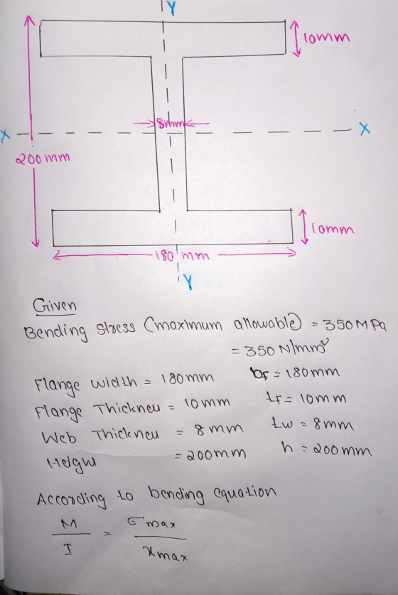
Consider an l beam shown in the figure shown in the quiz instruction. The maximum allowable...
QUESTION 4. For the beam shown in the figure, the maximum allowable bending stress is 180...
 QUESTION 4. For the beam shown in the figure, the maximum allowable bending stress is 180 MPa and the maximum allowable shear stress is 120 MPa. Choose an appropriate Wide Flange Section (W) that can carry the distributed force and the point force safely. 10 kN 8 kN/m C B 4 m 2 m
The built-up beam is made of steel as shown in Figure 1. Knowing that modulus of...
 The built-up beam is made of steel as shown in Figure 1. Knowing that modulus of elasticity for the steel is E = 200 GPa 150 mm 20 mm 150 mm 150 mm 10 mm M '10 mm 300 mm А Figure 1 (1) If the allowable tensile and compressive stress for the beam are allow tension = 140 MPa and o = 210 MPa. allow compression respectively, determine the maximum allowable internal moment M that can be applied Determine...
P8.008 The dimensions of the double-box beam cross section shown in the figure are b =...
 P8.008 The dimensions of the double-box beam cross section shown in the figure are b = 190 mm, d = 65 mm, and t = 3 mm. If the maximum allowable bending stress is 19 MPa, determine the maximum internal bending moment Mz magnitude that can be applied to the beam. Answer: Mz = N-m
3) (35 pts) A L-beam has the cross section shown. A moment M acts about the...
 3) (35 pts) A L-beam has the cross section shown. A moment M acts about the x-axis which passes through the centroid of the section. Determine the angle the neutral axis makes with respect to axis. Sketch it on the cross section. Given the design flexural stress limit is 100 MPa, determine the maximum allowable moment which can be applied. You only need to evaluate the stresses at points A, B. Helpful hint: Remember to change the sign of your...
A wooden beam is fabricated from three boards, which are fastened together with screws, as shown....
 A wooden beam is fabricated from three boards, which are fastened together with screws, as shown. The screws are uniformly spaced along the span of the beam at intervals of 260 mm. In service, the beam will be positioned so that bending occurs about the z axis. The maximum bending moment in the beam is Mz =ー3.54 kN-m, and the maximum shear force in the beam is vy =-3.67 kN. Assume s=260 mm, b1 = 33 mm, b2 = 200...
Figure Q3 shows a simply supported beam carrying a point load. The beam hasa rectangular hollow...
 Figure Q3 shows a simply supported beam carrying a point load. The beam hasa rectangular hollow steel section as shown in Figure Q3. a. Calculate the second moment of area of the section about the horizontal (10 marks) centroidal axis. Calculate the maximum allowable value of the point load Wif the elastic bending (15 marks) b. stress in the beam is to be limited to 250 MPa. c. Calculate the maximum shear stress at q-q in the beam when the...
answered to receive full credit. 3. (20 pts) For the L-section beam as shown in Fig-...
 answered to receive full credit. 3. (20 pts) For the L-section beam as shown in Fig- ure 3 which is subjected to a positive bending moment about the z-axis of 90 kN·m, determine 1. (20 pts) Consider the beam with loading shown in Figure 1. (a) Draw the shear and moment diagrams. (a) the location of the centroid (2,P) relative (b) If the beam is constructed from A-36 struc- tural steel, determine the minimum top and bottom section modulii such...
The simply-supported beam having I-beam cross-section as shown in figure is to carry a uniformly distributed...
 The simply-supported beam having I-beam cross-section as shown in figure is to carry a uniformly distributed load over its entire 1.2m length. Specify the maximum allowable load if the beam is made from malleable iron, ASTM A220, class 80002. The allowable tensile stress is 164 MPa and allowable compressive stress is 412 MPa. The centroid of the section is located at 35 mm from the bottom and moment of inertia are Ix = 2.66 x 10 mm". (a) Draw loading...
Problem 2 A T-beam is subjected to a moment M at the orientation shown: M? 150...
 Problem 2 A T-beam is subjected to a moment M at the orientation shown: M? 150 mm 50 mm Determine the orientation of the neutral axis measured from the positive z-axis. a) b) Determine the maximum value of M if the allowable tensile stress is 10 MPa and the allowable compressive stress is 7 MPa. 200 mm C
QUESTION 11 Knowing that for the extruded beam shown in the figure below, the allowable stress...
 QUESTION 11 Knowing that for the extruded beam shown in the figure below, the allowable stress is 120 MPa in tension and 150 MPa in compression. 125 mm N-A 50 mm 125 mm 150 mm The centroid () measured from bottom of cross-section is: [mm.] 114.7 138.25 151.32 163.17 NI QUESTION 12 The moment of inertia () around neutral axis (N.A.) is: [m 122.16x 10 5 165.56x 10 5 212.45x 10 6 310.11x 10 5
 QUESTION 4. For the beam shown in the figure, the maximum allowable bending stress is 180 MPa and the maximum allowable shear stress is 120 MPa. Choose an appropriate Wide Flange Section (W) that can carry the distributed force and the point force safely. 10 kN 8 kN/m C B 4 m 2 m
 The built-up beam is made of steel as shown in Figure 1. Knowing that modulus of elasticity for the steel is E = 200 GPa 150 mm 20 mm 150 mm 150 mm 10 mm M '10 mm 300 mm А Figure 1 (1) If the allowable tensile and compressive stress for the beam are allow tension = 140 MPa and o = 210 MPa. allow compression respectively, determine the maximum allowable internal moment M that can be applied Determine...
 P8.008 The dimensions of the double-box beam cross section shown in the figure are b = 190 mm, d = 65 mm, and t = 3 mm. If the maximum allowable bending stress is 19 MPa, determine the maximum internal bending moment Mz magnitude that can be applied to the beam. Answer: Mz = N-m
 3) (35 pts) A L-beam has the cross section shown. A moment M acts about the x-axis which passes through the centroid of the section. Determine the angle the neutral axis makes with respect to axis. Sketch it on the cross section. Given the design flexural stress limit is 100 MPa, determine the maximum allowable moment which can be applied. You only need to evaluate the stresses at points A, B. Helpful hint: Remember to change the sign of your...
 A wooden beam is fabricated from three boards, which are fastened together with screws, as shown. The screws are uniformly spaced along the span of the beam at intervals of 260 mm. In service, the beam will be positioned so that bending occurs about the z axis. The maximum bending moment in the beam is Mz =ー3.54 kN-m, and the maximum shear force in the beam is vy =-3.67 kN. Assume s=260 mm, b1 = 33 mm, b2 = 200...
 Figure Q3 shows a simply supported beam carrying a point load. The beam hasa rectangular hollow steel section as shown in Figure Q3. a. Calculate the second moment of area of the section about the horizontal (10 marks) centroidal axis. Calculate the maximum allowable value of the point load Wif the elastic bending (15 marks) b. stress in the beam is to be limited to 250 MPa. c. Calculate the maximum shear stress at q-q in the beam when the...
 answered to receive full credit. 3. (20 pts) For the L-section beam as shown in Fig- ure 3 which is subjected to a positive bending moment about the z-axis of 90 kN·m, determine 1. (20 pts) Consider the beam with loading shown in Figure 1. (a) Draw the shear and moment diagrams. (a) the location of the centroid (2,P) relative (b) If the beam is constructed from A-36 struc- tural steel, determine the minimum top and bottom section modulii such...
 The simply-supported beam having I-beam cross-section as shown in figure is to carry a uniformly distributed load over its entire 1.2m length. Specify the maximum allowable load if the beam is made from malleable iron, ASTM A220, class 80002. The allowable tensile stress is 164 MPa and allowable compressive stress is 412 MPa. The centroid of the section is located at 35 mm from the bottom and moment of inertia are Ix = 2.66 x 10 mm". (a) Draw loading...
 Problem 2 A T-beam is subjected to a moment M at the orientation shown: M? 150 mm 50 mm Determine the orientation of the neutral axis measured from the positive z-axis. a) b) Determine the maximum value of M if the allowable tensile stress is 10 MPa and the allowable compressive stress is 7 MPa. 200 mm C
 QUESTION 11 Knowing that for the extruded beam shown in the figure below, the allowable stress is 120 MPa in tension and 150 MPa in compression. 125 mm N-A 50 mm 125 mm 150 mm The centroid () measured from bottom of cross-section is: [mm.] 114.7 138.25 151.32 163.17 NI QUESTION 12 The moment of inertia () around neutral axis (N.A.) is: [m 122.16x 10 5 165.56x 10 5 212.45x 10 6 310.11x 10 5
Most questions answered within 3 hours.
-
.13 : Assume that we make an enhancement to a computer that
improves some mode of...
asked 42 seconds ago -
4)
Find the tension in an elevator cable if the 1000 kg elevator is
descending with...
asked 6 minutes ago -
A random sample of 51 newborn babies was taken at the Hospital.
The sample mean was...
asked 4 minutes ago -
Industry standards suggest that 16% of new vehicles require
warranty service within the first year. Jones...
asked 16 minutes ago -
1) Comment of this statement: “A compiler transforms high-level
language statements directly into object codes”.
asked 19 minutes ago -
Calculate the molality, mole-fraction and percent mass of 28.9M
HF at 25 degrees Celcius of the...
asked 28 minutes ago -
A developmental psychologist believes that children raised in
bilingual families will have higher verbal fluency at...
asked 34 minutes ago -
A fast food meal has 5660 kJ of energy. A person uses energy at
a rate...
asked 46 minutes ago -
The pKb for a generic amine(R-NH2)) in
aqueous solution is 6.30. What is its pKa?
asked 48 minutes ago -
The following reactions have the indicated equilibrium constants
at a particular temperature: N2(g) + O2(g) ⇌...
asked 50 minutes ago -
Please Help ASAP.
1Consider the below code which iterates over a linked
list of n nodes...
asked 1 hour ago -
Determine the air to fuel ratio of:
Canadian natural gas, with 93.9% methane, 4.2% ethane, 0.3%...
asked 1 hour ago