
Homework Answers

Add Answer to:
The circuit in the figure below has been connected for a long time. Let R1 =...
Switch S shown in the figure below has been closed for a long time, and the...
 Switch S shown in the figure below has been closed for a long time, and the electric circuit carries a constant current. Take C 3.00 F, C2 6.00 uF, R1 = 4.00 k, and R2 = 7.00 k. The power delivered to R2 is 2.00 W. R C - S R, (a) Find the charge on C. Q 222.18 Your response is within 10 % of the correct value. This may be due to roundoff error, or you could have...
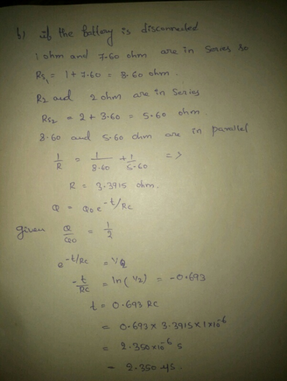
The switch in the circuit below has been closed for a very long time. 2. a....
 The switch in the circuit below has been closed for a very long
time. 2.
a. What is the voltage across the capacitor?
b. If the switch is opened, what is the time constant for
discharging the capacitor?
c. how long does it take the capacitor to discharge to 1/10th of
its initial voltage?
R1 = 1.00 Ω
R2 = 8.00 Ω
R3 = 4.00 Ω
R4 = 2.00 Ω
C = 1.00 μF
Battery = 10.0 V
R2 R4
The switch in the circuit below has been closed for a very long
time. 2.
a. What is the voltage across the capacitor?
b. If the switch is opened, what is the time constant for
discharging the capacitor?
c. how long does it take the capacitor to discharge to 1/10th of
its initial voltage?
R1 = 1.00 Ω
R2 = 8.00 Ω
R3 = 4.00 Ω
R4 = 2.00 Ω
C = 1.00 μF
Battery = 10.0 V
R2 R4
Madelyn and Scarlett decide to work a problem from the book. An RLC circuit has been...
 Madelyn and Scarlett decide to work a problem from the book. An RLC circuit has been set up as illustrated in the simulation. Initially, the switch S is at a, allowing the capacitor to charge. With the capacitor already fully charged, the switch is moved to b at time t = 0. As a result, the capacitor is being allowed to discharge through the resistor and the inductor. Find the frequency f of the oscillations in current that result, using...
1 = The figure below shows five resistors and two batteries connected in a circuit. What...
 1
= The figure below shows five resistors and two batteries connected in a circuit. What are the currents 11, 12, and 13? (Consider the following values: R1 1.2012, R2 = 2.08 12, R3 = 3.11 12, R4 = 4.04 N, R5 = 6.16 1. Due to the nature of this problem, do not use rounded intermediate values in your calculations—including answers submitted in WebAssign. Indicate the direction with the sign of your answer.) 1.2970 x 11 Your response is...
1
= The figure below shows five resistors and two batteries connected in a circuit. What are the currents 11, 12, and 13? (Consider the following values: R1 1.2012, R2 = 2.08 12, R3 = 3.11 12, R4 = 4.04 N, R5 = 6.16 1. Due to the nature of this problem, do not use rounded intermediate values in your calculations—including answers submitted in WebAssign. Indicate the direction with the sign of your answer.) 1.2970 x 11 Your response is...
The circuit shown in the figure below is connected for 2.70 min. (Assume R. = 8.80...
 The circuit shown in the figure below is connected for 2.70 min. (Assume R. = 8.80 N, R2 = 2.70 1, and V = 15.0 V.) 5.00 23.00 12 R2 } 1.00 12 R + -4.00 V - direction down (a) Determine the current in each branch of the circuit. branch magnitude (A) left X branch Your response differs from the correct answer by more than 10%. Double check your calculations. x middle Your response is within 10% of the...
At time t-0, an RC circuit consists of a 16.5-V emf device, a 68.0-Q resistor, and...
 At time t-0, an RC circuit consists of a 16.5-V emf device, a 68.0-Q resistor, and a 152.0-pF capacitor that is fully charged. The switch is thrown so that the capacitor begins to discharge (a) what is the time constant τ of this circuit? 1.1e-2 Your response is within 10% of the correct value. This may be due to roundoff error, or you could have a mistake in your calculation. Carry out all intermediate results to at least four-digit accuracy...
Consider the following figure. (Assume V-14 V, R1-2.3 Ω, and R2-1.5 Ω.) Ri 24 V 3.0...
 Consider the following figure. (Assume V-14 V, R1-2.3 Ω, and R2-1.5 Ω.) Ri 24 V 3.0 Ry (a) Can the circuit shown above be reduced to a single resistor connected to the batteries? Explain. No, because different currents flow thru each battery Score: 1 out of Comment: (b) Calculate each of the unknown currents 11, 12. and I3 for the circuit. (Give the magnitude of the current only.) 3.3163X -Your response is within 10% of the correct value. This may...
The two charges in the figure below are separated by d-3.50 cm. (Let q113.0 nC and...
 The two charges in the figure below are separated by d-3.50 cm. (Let q113.0 nC and q2 25.5 nC) 60.0° B 92 (a) Find the electric potential at point A 3.1 Your response is within 10% of the correct value. This may be due to roundoff error, or you could have a mistake in your calculation. Ca accuracy to minimize roundoff error. kV out all intermediate results to at least four-digit (b) Find the electric potential at point B, which...
The circuit in the figure below has been connected for a long time. Let R_1 =...
 The circuit in the figure below has been connected for a long time. Let R_1 = 7.20 Ohm and R_2 = 4.20 Ohm. What is the potential difference across the capacitor? If the battery is disconnected from the circuit, over what time interval does the capacitor discharge to one-tenth its initial voltage?
= 1.18 12, R2 = 2.20 2, R3 = 3.07 N, R4 = 4.16 1, R5...
 = 1.18 12, R2 = 2.20 2, R3 = 3.07 N, R4 = 4.16 1, R5 = 6.04 N. Due to the nature of this problem, do not use rounded intermediate The figure below shows five resistors and two batteries connected in a circuit. What are the currents 11, 12, and 13? (Consider the following values: R1 values in your calculations—including answers submitted in WebAssign. Indicate the direction with the sign of your answer.) 11 Your response is within 10%...
 Switch S shown in the figure below has been closed for a long time, and the electric circuit carries a constant current. Take C 3.00 F, C2 6.00 uF, R1 = 4.00 k, and R2 = 7.00 k. The power delivered to R2 is 2.00 W. R C - S R, (a) Find the charge on C. Q 222.18 Your response is within 10 % of the correct value. This may be due to roundoff error, or you could have...
 The switch in the circuit below has been closed for a very long
time. 2.
a. What is the voltage across the capacitor?
b. If the switch is opened, what is the time constant for
discharging the capacitor?
c. how long does it take the capacitor to discharge to 1/10th of
its initial voltage?
R1 = 1.00 Ω
R2 = 8.00 Ω
R3 = 4.00 Ω
R4 = 2.00 Ω
C = 1.00 μF
Battery = 10.0 V
R2 R4
The switch in the circuit below has been closed for a very long
time. 2.
a. What is the voltage across the capacitor?
b. If the switch is opened, what is the time constant for
discharging the capacitor?
c. how long does it take the capacitor to discharge to 1/10th of
its initial voltage?
R1 = 1.00 Ω
R2 = 8.00 Ω
R3 = 4.00 Ω
R4 = 2.00 Ω
C = 1.00 μF
Battery = 10.0 V
R2 R4
 Madelyn and Scarlett decide to work a problem from the book. An RLC circuit has been set up as illustrated in the simulation. Initially, the switch S is at a, allowing the capacitor to charge. With the capacitor already fully charged, the switch is moved to b at time t = 0. As a result, the capacitor is being allowed to discharge through the resistor and the inductor. Find the frequency f of the oscillations in current that result, using...
 1
= The figure below shows five resistors and two batteries connected in a circuit. What are the currents 11, 12, and 13? (Consider the following values: R1 1.2012, R2 = 2.08 12, R3 = 3.11 12, R4 = 4.04 N, R5 = 6.16 1. Due to the nature of this problem, do not use rounded intermediate values in your calculations—including answers submitted in WebAssign. Indicate the direction with the sign of your answer.) 1.2970 x 11 Your response is...
1
= The figure below shows five resistors and two batteries connected in a circuit. What are the currents 11, 12, and 13? (Consider the following values: R1 1.2012, R2 = 2.08 12, R3 = 3.11 12, R4 = 4.04 N, R5 = 6.16 1. Due to the nature of this problem, do not use rounded intermediate values in your calculations—including answers submitted in WebAssign. Indicate the direction with the sign of your answer.) 1.2970 x 11 Your response is...
 The circuit shown in the figure below is connected for 2.70 min. (Assume R. = 8.80 N, R2 = 2.70 1, and V = 15.0 V.) 5.00 23.00 12 R2 } 1.00 12 R + -4.00 V - direction down (a) Determine the current in each branch of the circuit. branch magnitude (A) left X branch Your response differs from the correct answer by more than 10%. Double check your calculations. x middle Your response is within 10% of the...
 At time t-0, an RC circuit consists of a 16.5-V emf device, a 68.0-Q resistor, and a 152.0-pF capacitor that is fully charged. The switch is thrown so that the capacitor begins to discharge (a) what is the time constant τ of this circuit? 1.1e-2 Your response is within 10% of the correct value. This may be due to roundoff error, or you could have a mistake in your calculation. Carry out all intermediate results to at least four-digit accuracy...
 Consider the following figure. (Assume V-14 V, R1-2.3 Ω, and R2-1.5 Ω.) Ri 24 V 3.0 Ry (a) Can the circuit shown above be reduced to a single resistor connected to the batteries? Explain. No, because different currents flow thru each battery Score: 1 out of Comment: (b) Calculate each of the unknown currents 11, 12. and I3 for the circuit. (Give the magnitude of the current only.) 3.3163X -Your response is within 10% of the correct value. This may...
 The two charges in the figure below are separated by d-3.50 cm. (Let q113.0 nC and q2 25.5 nC) 60.0° B 92 (a) Find the electric potential at point A 3.1 Your response is within 10% of the correct value. This may be due to roundoff error, or you could have a mistake in your calculation. Ca accuracy to minimize roundoff error. kV out all intermediate results to at least four-digit (b) Find the electric potential at point B, which...
 The circuit in the figure below has been connected for a long time. Let R_1 = 7.20 Ohm and R_2 = 4.20 Ohm. What is the potential difference across the capacitor? If the battery is disconnected from the circuit, over what time interval does the capacitor discharge to one-tenth its initial voltage?
 = 1.18 12, R2 = 2.20 2, R3 = 3.07 N, R4 = 4.16 1, R5 = 6.04 N. Due to the nature of this problem, do not use rounded intermediate The figure below shows five resistors and two batteries connected in a circuit. What are the currents 11, 12, and 13? (Consider the following values: R1 values in your calculations—including answers submitted in WebAssign. Indicate the direction with the sign of your answer.) 11 Your response is within 10%...
Most questions answered within 3 hours.
-
A 10.000 g sample of water contains 11.19% H by mass. what
should be the %H...
asked 3 minutes ago -
Consider an investment game among 2 players. Each player can
either invest,
i, or not invest,-i....
asked 1 minute ago -
The time taken to complete a particular task is normally
distributed with a standard deviation of...
asked 11 minutes ago -
we have heteroskedasticity in a regression when:
When the variance of error terms changes when an...
asked 20 minutes ago -
Explain some different types of fungi. State the different
divisions undergo by fungi.
asked 33 minutes ago -
The shortest time that 120 C can flow through a 20 A circuit
breaker without tripping...
asked 34 minutes ago -
A software design pattern is a general, reusable solution to a
commonly occurring problem, acting as...
asked 36 minutes ago -
The mean waiting time at the drive-through of a fast-food
restaurant from the time an order...
asked 53 minutes ago -
The pitch (p) of a helix is defined as p = dn, in which n is...
asked 55 minutes ago -
Do you agree that the declining stock of social capital is the
blame for the failure...
asked 58 minutes ago -
A researcher is interested in whether coffee consumption helps
with performance on reading comprehension tasks. The...
asked 1 hour ago -
it has been estimated since the beginning of the human race that
about 133 metric ton...
asked 1 hour ago