
Homework Answers
Since there is no rotation in the shaft supported and also there is assumed no friction at the bearings A and B, we will apply simple torque balance equations at the sprockets and get the value of F.
Add Answer to:
Figure 3 4. Figure 4 shows a 1.5 in diameter shaft supported by self-aligning ball bearings...
Figure 3 4. Figure 4 shows a 1.5 in diameter shaft supported by self-aligning ball bearings A and B. There are two chai...
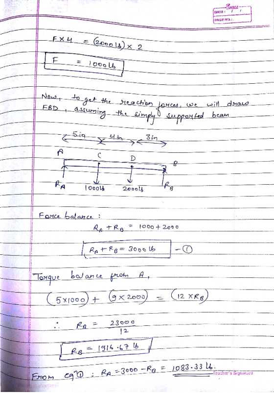
 Figure 3 4. Figure 4 shows a 1.5 in diameter shaft supported by self-aligning ball bearings A and B. There are two chain sprockets, which are attached to the shaft and loaded as shown. Determine the force F. Model this shaft as a simply supported beam. Determine the bearing reactions RA and RB. (OC: A, E), (Ans: RA 1083.3, RB 1916.67 lb,) SHAFT SPROCKET # \ SPROc KET+#2 2 in, 2000 lb 3 in. 4 in. Sin
Figure 3 4....
Figure 3 4. Figure 4 shows a 1.5 in diameter shaft supported by self-aligning ball bearings A and B. There are two chain sprockets, which are attached to the shaft and loaded as shown. Determine the force F. Model this shaft as a simply supported beam. Determine the bearing reactions RA and RB. (OC: A, E), (Ans: RA 1083.3, RB 1916.67 lb,) SHAFT SPROCKET # \ SPROc KET+#2 2 in, 2000 lb 3 in. 4 in. Sin
Figure 3 4....
The rotating shaft shown below is supported by self aligning bearings at A and D. The diameter of...
 The rotating shaft shown below is supported by self aligning bearings at A and D. The diameter of the shaft changes from D-1.5" to d-1.0" at the midpoint of the shaft. The radius of the fillet at the diameter change is r-0.2" and all surfaces are machined. The shaft is made of normalized 1020 steel having . 64.0 ksi and S, = 50.3 ksi . The shaft is loaded with 250-lb forces at B and C as shown to create...
Explanations and formulas used are greatly appreciated. The figure below shows a 1-in. solid round shaft...
 Explanations and formulas used are greatly appreciated.
The figure below shows a 1-in. solid round shaft supported by self-aligning bearings at A and B. Attached to the shaft are two chain sprockets that are loaded as shown. What tensile yield strength must a ductile material have in order to provide a safety factor of 3 with respect to initial yielding at the point of the highest stress using the maximum- distortion-energy theory. Take F1 332 lb and F2 2F1. Submit...
Explanations and formulas used are greatly appreciated.
The figure below shows a 1-in. solid round shaft supported by self-aligning bearings at A and B. Attached to the shaft are two chain sprockets that are loaded as shown. What tensile yield strength must a ductile material have in order to provide a safety factor of 3 with respect to initial yielding at the point of the highest stress using the maximum- distortion-energy theory. Take F1 332 lb and F2 2F1. Submit...
answer with steps please 4. Figure below shows a rotating shaft simply supported in ball bearings...
 answer with steps please
4. Figure below shows a rotating shaft simply supported in ball bearings at A and D and loaded by a nonrotating force F of 6.8 kN. The shaft is made AISI/SAE cold drawn 1050 steel, estimate the life of the part. 550 C 400 B - 6.8 EN 75 -100 - 250 --- -125 Stress amplitude (MPa) 10 10 10 10 10 Fatigue life cycles) 10
answer with steps please
4. Figure below shows a rotating shaft simply supported in ball bearings at A and D and loaded by a nonrotating force F of 6.8 kN. The shaft is made AISI/SAE cold drawn 1050 steel, estimate the life of the part. 550 C 400 B - 6.8 EN 75 -100 - 250 --- -125 Stress amplitude (MPa) 10 10 10 10 10 Fatigue life cycles) 10
machine elements QUESTION-3 Shaft shown in the figure is supported by A and C bearings. Bearing...
 machine elements
QUESTION-3 Shaft shown in the figure is supported by A and C bearings. Bearing A has 4300 N radial and 1400 N axial force due to the tooth force of the gear wheel on the shaft. Only a radial force of 3100 N acts on bearing C. The shaft diameters are the same in the region where the A and C bearings are located and dA = dC = 35 mm The rotation speed of the spindle is...
machine elements
QUESTION-3 Shaft shown in the figure is supported by A and C bearings. Bearing A has 4300 N radial and 1400 N axial force due to the tooth force of the gear wheel on the shaft. Only a radial force of 3100 N acts on bearing C. The shaft diameters are the same in the region where the A and C bearings are located and dA = dC = 35 mm The rotation speed of the spindle is...
ME 350-001 STATIC MACHINE COMPONENTS Spring 2019 Dr. Todd January 18, 2019 Shear and Bending Moment...
 ME 350-001 STATIC MACHINE COMPONENTS Spring 2019 Dr. Todd January 18, 2019 Shear and Bending Moment Diagrams The figure shows a 1-in. solid round shaft supported by self-aligning bearings at A and B. Attached to the shaft are two chair sprockets that are loaded as show. Treat this as a static loading problem, ignoring fatigue and stress concentrations. Also, ignore the shear load and stress. Draw shear force and bending moment diagrams and determine the magnitude and location of the...
The figure shows a transmission shaft. The steel solid shaft is 200 mm long between self-aligning...
 The figure shows a transmission shaft. The steel solid shaft is 200 mm long between self-aligning bearings at A and B. Belt forces in the same horizontal direction) are applied to a 120-mm diameter sheave at C. The left end of the shaft is connected to an electric motor attached to a clutch by means of a flexible coupling. Nothing is attached to the right end (it is free). Assuming the shaft has a constant diameter, d. (a) Perform the...
Figure below shows the load components acting on a helical gear mounted on a simply supported...
 Figure below shows the load components acting on a helical gear
mounted on a simply
supported shaft. Bearing B takes thrust. A flexible coupling for
transmitting
torque attaches to the right end of the shaft. The left end is
free.
1-Draw load, shear force, and bending moment diagrams for the
shaft, in both the horizontal and vertical planes.
2- Identify the most critically loaded shaft cross section, and
for this location determine the diameter theoretically required for
infinite life. Assume...
Figure below shows the load components acting on a helical gear
mounted on a simply
supported shaft. Bearing B takes thrust. A flexible coupling for
transmitting
torque attaches to the right end of the shaft. The left end is
free.
1-Draw load, shear force, and bending moment diagrams for the
shaft, in both the horizontal and vertical planes.
2- Identify the most critically loaded shaft cross section, and
for this location determine the diameter theoretically required for
infinite life. Assume...
The figure shows a transmission shaft. The steel solid shaft is 200 mm long between self-aligning...
 The figure shows a transmission shaft. The steel solid shaft is 200 mm long between self-aligning bearings at A and B. Belt forces (in the same horizontal direction) are applied to a 120-mm diameter sheave at C. The left end of the shaft is connected to an electric motor attached to a clutch by means of a flexible coupling. Nothing is attached to the right end (it is free). Assuming the shaft has a constant diameter, d, (a) Perform the...
The following figure shows a rotating system in which the shaft is supported in bearings at A and B. The three masses m...
 The following figure shows a rotating system in which the shaft is supported in bearings at A and B. The three masses mi, m2, and m3 are connected to the shaft as indicated in the figure. a) Find the bearing reactions at A and B if the speed of the shaft is 1000 rpm. b) Determine the locations and magnitudes of the balancing masses to be placed at a radius of 0.25 m in the planes L and R, which...
 Figure 3 4. Figure 4 shows a 1.5 in diameter shaft supported by self-aligning ball bearings A and B. There are two chain sprockets, which are attached to the shaft and loaded as shown. Determine the force F. Model this shaft as a simply supported beam. Determine the bearing reactions RA and RB. (OC: A, E), (Ans: RA 1083.3, RB 1916.67 lb,) SHAFT SPROCKET # \ SPROc KET+#2 2 in, 2000 lb 3 in. 4 in. Sin
Figure 3 4....
Figure 3 4. Figure 4 shows a 1.5 in diameter shaft supported by self-aligning ball bearings A and B. There are two chain sprockets, which are attached to the shaft and loaded as shown. Determine the force F. Model this shaft as a simply supported beam. Determine the bearing reactions RA and RB. (OC: A, E), (Ans: RA 1083.3, RB 1916.67 lb,) SHAFT SPROCKET # \ SPROc KET+#2 2 in, 2000 lb 3 in. 4 in. Sin
Figure 3 4....
 The rotating shaft shown below is supported by self aligning bearings at A and D. The diameter of the shaft changes from D-1.5" to d-1.0" at the midpoint of the shaft. The radius of the fillet at the diameter change is r-0.2" and all surfaces are machined. The shaft is made of normalized 1020 steel having . 64.0 ksi and S, = 50.3 ksi . The shaft is loaded with 250-lb forces at B and C as shown to create...
 Explanations and formulas used are greatly appreciated.
The figure below shows a 1-in. solid round shaft supported by self-aligning bearings at A and B. Attached to the shaft are two chain sprockets that are loaded as shown. What tensile yield strength must a ductile material have in order to provide a safety factor of 3 with respect to initial yielding at the point of the highest stress using the maximum- distortion-energy theory. Take F1 332 lb and F2 2F1. Submit...
Explanations and formulas used are greatly appreciated.
The figure below shows a 1-in. solid round shaft supported by self-aligning bearings at A and B. Attached to the shaft are two chain sprockets that are loaded as shown. What tensile yield strength must a ductile material have in order to provide a safety factor of 3 with respect to initial yielding at the point of the highest stress using the maximum- distortion-energy theory. Take F1 332 lb and F2 2F1. Submit...
 answer with steps please
4. Figure below shows a rotating shaft simply supported in ball bearings at A and D and loaded by a nonrotating force F of 6.8 kN. The shaft is made AISI/SAE cold drawn 1050 steel, estimate the life of the part. 550 C 400 B - 6.8 EN 75 -100 - 250 --- -125 Stress amplitude (MPa) 10 10 10 10 10 Fatigue life cycles) 10
answer with steps please
4. Figure below shows a rotating shaft simply supported in ball bearings at A and D and loaded by a nonrotating force F of 6.8 kN. The shaft is made AISI/SAE cold drawn 1050 steel, estimate the life of the part. 550 C 400 B - 6.8 EN 75 -100 - 250 --- -125 Stress amplitude (MPa) 10 10 10 10 10 Fatigue life cycles) 10
 machine elements
QUESTION-3 Shaft shown in the figure is supported by A and C bearings. Bearing A has 4300 N radial and 1400 N axial force due to the tooth force of the gear wheel on the shaft. Only a radial force of 3100 N acts on bearing C. The shaft diameters are the same in the region where the A and C bearings are located and dA = dC = 35 mm The rotation speed of the spindle is...
machine elements
QUESTION-3 Shaft shown in the figure is supported by A and C bearings. Bearing A has 4300 N radial and 1400 N axial force due to the tooth force of the gear wheel on the shaft. Only a radial force of 3100 N acts on bearing C. The shaft diameters are the same in the region where the A and C bearings are located and dA = dC = 35 mm The rotation speed of the spindle is...
 ME 350-001 STATIC MACHINE COMPONENTS Spring 2019 Dr. Todd January 18, 2019 Shear and Bending Moment Diagrams The figure shows a 1-in. solid round shaft supported by self-aligning bearings at A and B. Attached to the shaft are two chair sprockets that are loaded as show. Treat this as a static loading problem, ignoring fatigue and stress concentrations. Also, ignore the shear load and stress. Draw shear force and bending moment diagrams and determine the magnitude and location of the...
 The figure shows a transmission shaft. The steel solid shaft is 200 mm long between self-aligning bearings at A and B. Belt forces in the same horizontal direction) are applied to a 120-mm diameter sheave at C. The left end of the shaft is connected to an electric motor attached to a clutch by means of a flexible coupling. Nothing is attached to the right end (it is free). Assuming the shaft has a constant diameter, d. (a) Perform the...
 Figure below shows the load components acting on a helical gear
mounted on a simply
supported shaft. Bearing B takes thrust. A flexible coupling for
transmitting
torque attaches to the right end of the shaft. The left end is
free.
1-Draw load, shear force, and bending moment diagrams for the
shaft, in both the horizontal and vertical planes.
2- Identify the most critically loaded shaft cross section, and
for this location determine the diameter theoretically required for
infinite life. Assume...
Figure below shows the load components acting on a helical gear
mounted on a simply
supported shaft. Bearing B takes thrust. A flexible coupling for
transmitting
torque attaches to the right end of the shaft. The left end is
free.
1-Draw load, shear force, and bending moment diagrams for the
shaft, in both the horizontal and vertical planes.
2- Identify the most critically loaded shaft cross section, and
for this location determine the diameter theoretically required for
infinite life. Assume...
 The figure shows a transmission shaft. The steel solid shaft is 200 mm long between self-aligning bearings at A and B. Belt forces (in the same horizontal direction) are applied to a 120-mm diameter sheave at C. The left end of the shaft is connected to an electric motor attached to a clutch by means of a flexible coupling. Nothing is attached to the right end (it is free). Assuming the shaft has a constant diameter, d, (a) Perform the...
 The following figure shows a rotating system in which the shaft is supported in bearings at A and B. The three masses mi, m2, and m3 are connected to the shaft as indicated in the figure. a) Find the bearing reactions at A and B if the speed of the shaft is 1000 rpm. b) Determine the locations and magnitudes of the balancing masses to be placed at a radius of 0.25 m in the planes L and R, which...
Most questions answered within 3 hours.
-
A study of the effects of exercise used rats bred to have high
or low capacity...
asked 11 minutes ago -
Using your data from the experiment, calculate the initial moles
of HCl that you started with....
asked 11 minutes ago -
Suppose you want to make 500 mL of a 0.20 M Tris buffer at pH
8.0....
asked 13 minutes ago -
The titanic hit an iceberg estimated to be half of her mass.
Before hitting the iceberg,...
asked 34 minutes ago -
3. The top four firms in Industry A have market shares of 30,
25, 10, and...
asked 37 minutes ago -
Are there such things as microscopic multicellular animal
parasites? If so, please give examples.
asked 1 hour ago -
1. What two structures in the ear are involved in your
sense of balance and in...
asked 59 minutes ago -
Two ice skaters suddenly push off against one another starting
from a stationary position. The 45...
asked 1 hour ago -
What is the Larmor frequency for a proton in a magnetic field of
B0 = 14.0...
asked 1 hour ago -
Problem 03.019 Annual Worth Calculations
Find the value of x that makes the equivalent annual
worth...
asked 1 hour ago -
Under common law, right of survivorship was automatically a
feature of which type of co-tenancy?
a....
asked 1 hour ago -
At 1 bar, how much energy is required to heat 61.0 g of H2O(s)
at −12.0...
asked 1 hour ago