
Homework Answers
Add Answer to:
Computer Problem # 3 The common configuration of an internal combustion engine is represented by a...
The connecting rod AB of a certain internal-combustion engine weighs 1.24 lb with mass center at...
 The connecting rod AB of a certain internal-combustion engine weighs 1.24 lb with mass center at G and has a radius of gyration about G of 1.20 in. The piston and piston pin A together weigh 1.96 lb. The engine (link OB) is running at a constant speed of 2040 rev/min. Neglect the weights of the components and the force exerted by the gas in the cylinder compared with the dynamic forces generated and calculate the magnitude of the force...
For the engine system of Prob. 15.C3 of Chap. 15, the masses of piston P and the connecting rod B...
 For the engine system of Prob. 15.C3 of Chap. 15, the masses of piston P and the connecting rod BD are 2.5 kg and 3 kg, respectively. Knowing that during a test of the system no force is applied to the face of the piston, use computational software to calculate and plot the horizontal and vertical components of the dynamic reactions exerted on the connecting rod at B and D for values of from 0 to 180° Prob. 15.C3 In...
Problem 2 The data of a slider-crank mechanism are given below. Crank: r 3.13 in rz (ra) = 0.38r, (02-1500 rpm 1 = 12.5 in. To3 (la)-0.4I m2-0.060 blob Crank pin wrist pin Connecting rod Gas pres...
 Problem 2 The data of a slider-crank mechanism are given below. Crank: r 3.13 in rz (ra) = 0.38r, (02-1500 rpm 1 = 12.5 in. To3 (la)-0.4I m2-0.060 blob Crank pin wrist pin Connecting rod Gas pressure Conrod: a, 03, Piston: m-0.015 blob Crank (a) Write on papers step by step to calculate the inertia force and inertia torque for a crank position θ,-22°. Main pin Piston Cylinder (b) Develop a MATLAB program to calculate and plot the inertia force...
Could i get help writing the code for this question in matlab? An internal combustion engine...
 Could i get help writing the code for this question in
matlab?
An internal combustion engine slider-crank mechanism is shown in the figure. Crank AB rotates in selected clockwise positive direction as shown. Piston position is Y=AD. o(t) is angular position of the crank, 0(t) is angular velocity of the crank, ő is angular acceleration of the crank. Crank AB rotates with a constant angular velocity of 5 rad/s clockwise in positive O direction as shown. Perform computer simulations using...
Could i get help writing the code for this question in
matlab?
An internal combustion engine slider-crank mechanism is shown in the figure. Crank AB rotates in selected clockwise positive direction as shown. Piston position is Y=AD. o(t) is angular position of the crank, 0(t) is angular velocity of the crank, ő is angular acceleration of the crank. Crank AB rotates with a constant angular velocity of 5 rad/s clockwise in positive O direction as shown. Perform computer simulations using...
An internal combustion engine slider-crank mechanism is shown in the figure. Crank AB rotates in selected...
 An internal combustion engine slider-crank mechanism is shown in the figure. Crank AB rotates in selected clockwise positive direction as shown. Piston position is Y=AD. e(t) is angular position of the crank, ó(t) is angular velocity of the crank, ő is angular acceleration of the crank, 4) Crank AB rotates starting from rest with a constant angular acceleration of 0.25 rad/sec? ( = 0.25 rad/sec² ) clockwise in positive 0 direction as shown Perform computer simulations using above formulas to...
i want just (F) 2. (40 points) In the engine mechanism shown in fig. 2, the...
 i want just (F)
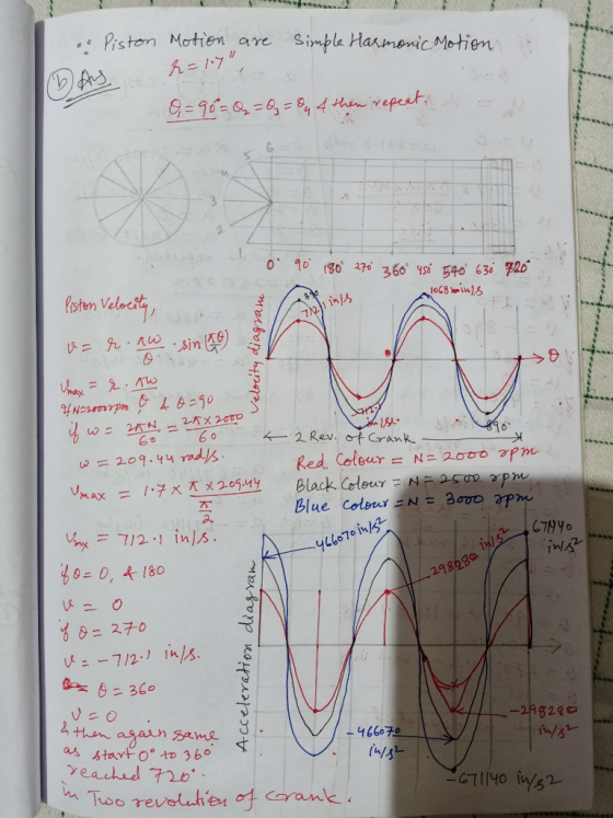
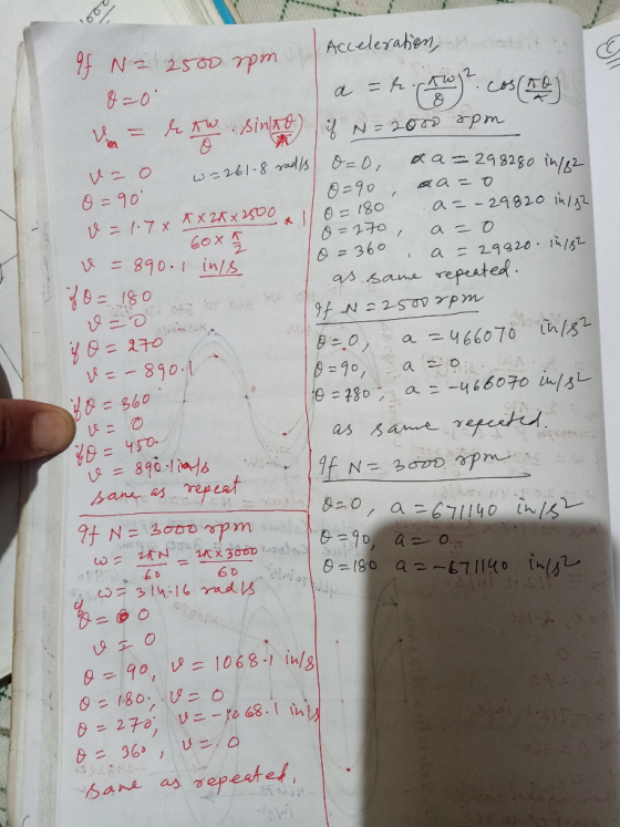
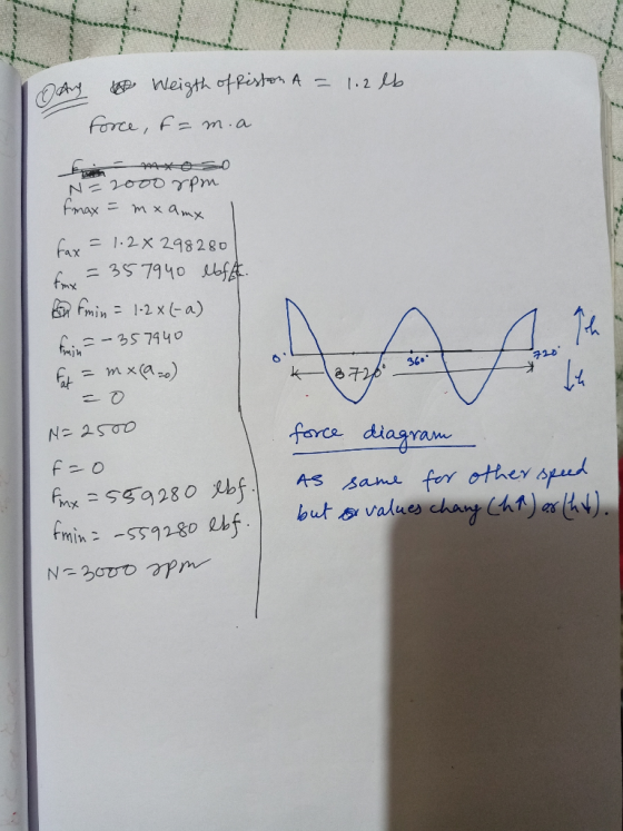
2. (40 points) In the engine mechanism shown in fig. 2, the crank AB has a constant clockwise angular velocity of 2000 rpm.And the connecting rod is a uniform, slender rod whose center of mass is in its geometric center G. For the crank position shown determine l 8 in 3in Figure 2: Problem 2 (a) (2.5 points) The velocity of B (b) (5 points) The angular velocity of the connecting rod BD, and the velocity...
i want just (F)
2. (40 points) In the engine mechanism shown in fig. 2, the crank AB has a constant clockwise angular velocity of 2000 rpm.And the connecting rod is a uniform, slender rod whose center of mass is in its geometric center G. For the crank position shown determine l 8 in 3in Figure 2: Problem 2 (a) (2.5 points) The velocity of B (b) (5 points) The angular velocity of the connecting rod BD, and the velocity...
DYNAMICS An internal combustion engine slider-crank mechanism is shown in the figure. Crank AB rotates in...
 DYNAMICS
An internal combustion engine slider-crank mechanism is shown in the figure. Crank AB rotates in selected clockwise positive direction as shown. Piston position is Y=AD. e(t) is angular position of the crank, ó(t) is angular velocity of the crank, ő is angular acceleration of the crank, y Р D 150 mm А e B - - X 50 mm 5) Crank AB rotates starting from rest with a constant angular acceleration of 0.25 rad/sec? ( = 0.25 rad/sec? )...
DYNAMICS
An internal combustion engine slider-crank mechanism is shown in the figure. Crank AB rotates in selected clockwise positive direction as shown. Piston position is Y=AD. e(t) is angular position of the crank, ó(t) is angular velocity of the crank, ő is angular acceleration of the crank, y Р D 150 mm А e B - - X 50 mm 5) Crank AB rotates starting from rest with a constant angular acceleration of 0.25 rad/sec? ( = 0.25 rad/sec? )...
please solve 1 (1,2) theory of machines KHematic Analysis &Synthesis Assume data if missing) 1. One cylinder of a rotary engine is shown in the configuration diagram shown in Figure Time:3hrs...
 please solve 1 (1,2) theory of machines
KHematic Analysis &Synthesis Assume data if missing) 1. One cylinder of a rotary engine is shown in the configuration diagram shown in Figure Time:3hrs (Answer any five from the following Full marks: 100 below. OA is the fixed crank, 200 mm long. OP is the connecting rod and is $20 mm long. The line of stroke is along AR and at the instant is inclined at 30° to the vertical. The body of...
please solve 1 (1,2) theory of machines
KHematic Analysis &Synthesis Assume data if missing) 1. One cylinder of a rotary engine is shown in the configuration diagram shown in Figure Time:3hrs (Answer any five from the following Full marks: 100 below. OA is the fixed crank, 200 mm long. OP is the connecting rod and is $20 mm long. The line of stroke is along AR and at the instant is inclined at 30° to the vertical. The body of...
0 Required information Problem 16.138 General plane motion: System of rigid bodies: Rod and piston DEPENDENT...
 0 Required information Problem 16.138 General plane motion: System of rigid bodies: Rod and piston DEPENDENT MULTI PART PROBLEM - ASSIGN ALL PARTS NOTE: This is a multi-part question. Once an answer is submitted, you will be unable to return to this part. In the engine system shown, /=250 mm and b=100 mm. The connecting rod BD is assumed to be a 1.7-kg uniform slender rod and is attached to the 1.8-kg piston During a test of the system, crank...
Problem 3.3 In the engine system shown, the crank AB has a constant counterclockwise angular velocity of 200 rad/s...
 Problem 3.3 In the engine system shown, the crank AB has a constant counterclockwise angular velocity of 200 rad/s. Assume that AB-75mm and BD-200 mm. For the crank position indicated determine (a) the angular velocity of the connecting rod BD, (b) the angular acceleration of the connecting rod BD and (c) the velocity and the acceleration of point D. Problem 3.4 A thin homogeneous wire with Determine the period of small oscillation if the wire (a) is suspended as shown,...
 The connecting rod AB of a certain internal-combustion engine weighs 1.24 lb with mass center at G and has a radius of gyration about G of 1.20 in. The piston and piston pin A together weigh 1.96 lb. The engine (link OB) is running at a constant speed of 2040 rev/min. Neglect the weights of the components and the force exerted by the gas in the cylinder compared with the dynamic forces generated and calculate the magnitude of the force...
 For the engine system of Prob. 15.C3 of Chap. 15, the masses of piston P and the connecting rod BD are 2.5 kg and 3 kg, respectively. Knowing that during a test of the system no force is applied to the face of the piston, use computational software to calculate and plot the horizontal and vertical components of the dynamic reactions exerted on the connecting rod at B and D for values of from 0 to 180° Prob. 15.C3 In...
 Problem 2 The data of a slider-crank mechanism are given below. Crank: r 3.13 in rz (ra) = 0.38r, (02-1500 rpm 1 = 12.5 in. To3 (la)-0.4I m2-0.060 blob Crank pin wrist pin Connecting rod Gas pressure Conrod: a, 03, Piston: m-0.015 blob Crank (a) Write on papers step by step to calculate the inertia force and inertia torque for a crank position θ,-22°. Main pin Piston Cylinder (b) Develop a MATLAB program to calculate and plot the inertia force...
 Could i get help writing the code for this question in
matlab?
An internal combustion engine slider-crank mechanism is shown in the figure. Crank AB rotates in selected clockwise positive direction as shown. Piston position is Y=AD. o(t) is angular position of the crank, 0(t) is angular velocity of the crank, ő is angular acceleration of the crank. Crank AB rotates with a constant angular velocity of 5 rad/s clockwise in positive O direction as shown. Perform computer simulations using...
Could i get help writing the code for this question in
matlab?
An internal combustion engine slider-crank mechanism is shown in the figure. Crank AB rotates in selected clockwise positive direction as shown. Piston position is Y=AD. o(t) is angular position of the crank, 0(t) is angular velocity of the crank, ő is angular acceleration of the crank. Crank AB rotates with a constant angular velocity of 5 rad/s clockwise in positive O direction as shown. Perform computer simulations using...
 An internal combustion engine slider-crank mechanism is shown in the figure. Crank AB rotates in selected clockwise positive direction as shown. Piston position is Y=AD. e(t) is angular position of the crank, ó(t) is angular velocity of the crank, ő is angular acceleration of the crank, 4) Crank AB rotates starting from rest with a constant angular acceleration of 0.25 rad/sec? ( = 0.25 rad/sec² ) clockwise in positive 0 direction as shown Perform computer simulations using above formulas to...
 i want just (F)
2. (40 points) In the engine mechanism shown in fig. 2, the crank AB has a constant clockwise angular velocity of 2000 rpm.And the connecting rod is a uniform, slender rod whose center of mass is in its geometric center G. For the crank position shown determine l 8 in 3in Figure 2: Problem 2 (a) (2.5 points) The velocity of B (b) (5 points) The angular velocity of the connecting rod BD, and the velocity...
i want just (F)
2. (40 points) In the engine mechanism shown in fig. 2, the crank AB has a constant clockwise angular velocity of 2000 rpm.And the connecting rod is a uniform, slender rod whose center of mass is in its geometric center G. For the crank position shown determine l 8 in 3in Figure 2: Problem 2 (a) (2.5 points) The velocity of B (b) (5 points) The angular velocity of the connecting rod BD, and the velocity...
 DYNAMICS
An internal combustion engine slider-crank mechanism is shown in the figure. Crank AB rotates in selected clockwise positive direction as shown. Piston position is Y=AD. e(t) is angular position of the crank, ó(t) is angular velocity of the crank, ő is angular acceleration of the crank, y Р D 150 mm А e B - - X 50 mm 5) Crank AB rotates starting from rest with a constant angular acceleration of 0.25 rad/sec? ( = 0.25 rad/sec? )...
DYNAMICS
An internal combustion engine slider-crank mechanism is shown in the figure. Crank AB rotates in selected clockwise positive direction as shown. Piston position is Y=AD. e(t) is angular position of the crank, ó(t) is angular velocity of the crank, ő is angular acceleration of the crank, y Р D 150 mm А e B - - X 50 mm 5) Crank AB rotates starting from rest with a constant angular acceleration of 0.25 rad/sec? ( = 0.25 rad/sec? )...
 please solve 1 (1,2) theory of machines
KHematic Analysis &Synthesis Assume data if missing) 1. One cylinder of a rotary engine is shown in the configuration diagram shown in Figure Time:3hrs (Answer any five from the following Full marks: 100 below. OA is the fixed crank, 200 mm long. OP is the connecting rod and is $20 mm long. The line of stroke is along AR and at the instant is inclined at 30° to the vertical. The body of...
please solve 1 (1,2) theory of machines
KHematic Analysis &Synthesis Assume data if missing) 1. One cylinder of a rotary engine is shown in the configuration diagram shown in Figure Time:3hrs (Answer any five from the following Full marks: 100 below. OA is the fixed crank, 200 mm long. OP is the connecting rod and is $20 mm long. The line of stroke is along AR and at the instant is inclined at 30° to the vertical. The body of...
 0 Required information Problem 16.138 General plane motion: System of rigid bodies: Rod and piston DEPENDENT MULTI PART PROBLEM - ASSIGN ALL PARTS NOTE: This is a multi-part question. Once an answer is submitted, you will be unable to return to this part. In the engine system shown, /=250 mm and b=100 mm. The connecting rod BD is assumed to be a 1.7-kg uniform slender rod and is attached to the 1.8-kg piston During a test of the system, crank...
 Problem 3.3 In the engine system shown, the crank AB has a constant counterclockwise angular velocity of 200 rad/s. Assume that AB-75mm and BD-200 mm. For the crank position indicated determine (a) the angular velocity of the connecting rod BD, (b) the angular acceleration of the connecting rod BD and (c) the velocity and the acceleration of point D. Problem 3.4 A thin homogeneous wire with Determine the period of small oscillation if the wire (a) is suspended as shown,...
Most questions answered within 3 hours.
-
A regression equation that describes the relationship between
the amount of the bill ($) at a...
asked 1 minute ago -
284 mL of a 0.52 M potassium hydroxide solution is added to 467
mL of a...
asked 29 minutes ago -
exercise on VSEPR and molecular structrue.
octahedral
SeCl62-
TeCl62-
ClF62-
distorted
SeF62–
IF6–
asked 30 minutes ago -
Little’s Law: Val d’Costa is a world famous ski village in the
French Alps. Because of...
asked 1 hour ago -
Find the absolute error D for the calculation if A + B/C=D A=
9.4 +/- 0.4...
asked 1 hour ago -
New Air Heating and Cooling, manufactures furnaces and central
air units. The company pride itself on...
asked 1 hour ago -
A coach uses a new technique to train gymnasts. Seven
gymnasts were randomly selected and their...
asked 3 hours ago -
While rotating the tires on your car you notice a rock [mass =
0.1 Kg] stuck...
asked 5 hours ago -
Using MARS simulator, write MIPS programs according to
the following scenarios: Receive a positive integer number...
asked 7 hours ago -
An object in front of a concave mirror has a real image that is
11.5 cm...
asked 7 hours ago -
Consider the reaction, C3 H8 + O2 --> CO2 + H2O. How many
moles of O2...
asked 9 hours ago -
You and your opponent both roll a fair die. If you both roll the
same number,...
asked 9 hours ago