
Homework Answers
Add Answer to:
For the engine system of Prob. 15.C3 of Chap. 15, the masses of piston P and the connecting rod B...
In the engine system shown, 1 - 160 mm and b 60 mm. Knowing that crank AB rotates with a constant...
 can you work it out step by step please. I really need
help
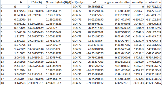
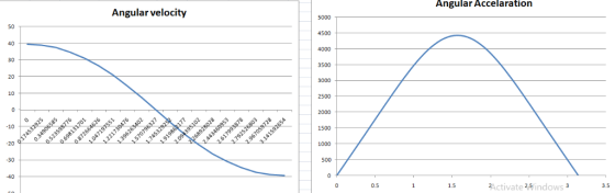
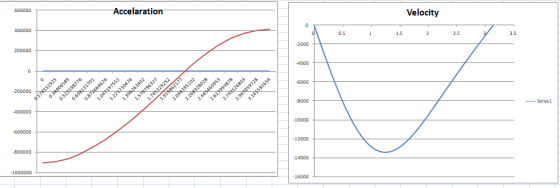
In the engine system shown, 1 - 160 mm and b 60 mm. Knowing that crank AB rotates with a constant angular velocity of 1000 rpm clockwise, use computational software to determine and plot for values of 0 from 0 to 180° and using 10° increments, (a) the angular velocity and angular acceleration of rod BD, (b) the velocity and acceleration of the piston F.
In the...
can you work it out step by step please. I really need
help
In the engine system shown, 1 - 160 mm and b 60 mm. Knowing that crank AB rotates with a constant angular velocity of 1000 rpm clockwise, use computational software to determine and plot for values of 0 from 0 to 180° and using 10° increments, (a) the angular velocity and angular acceleration of rod BD, (b) the velocity and acceleration of the piston F.
In the...
Please show ALL work and answer ALL parts In the engine system shown -250 mm and b 100 mm. The connecting rod BD is assumed to be a 1.2-kg uniform slender rod and is attached to the 1.8-kg piston...
 Please show ALL work and answer ALL parts
In the engine system shown -250 mm and b 100 mm. The connecting rod BD is assumed to be a 1.2-kg uniform slender rod and is attached to the 1.8-kg piston P. The AB rod is rotating counterclockwise at a constant angular velocity of 15 rads/s. Determine all the reactionary forces as a function of θ and plot these forces as a function of θ. At what angle(s) is the reaction force...
Please show ALL work and answer ALL parts
In the engine system shown -250 mm and b 100 mm. The connecting rod BD is assumed to be a 1.2-kg uniform slender rod and is attached to the 1.8-kg piston P. The AB rod is rotating counterclockwise at a constant angular velocity of 15 rads/s. Determine all the reactionary forces as a function of θ and plot these forces as a function of θ. At what angle(s) is the reaction force...
15.C1 The disk shown has a constant angular velocity of 500 rpm coun terclockwise. Knowing that...
 15.C1 The disk shown has a constant angular velocity of 500 rpm coun terclockwise. Knowing that rod BD is 250 mm long, use computational software to determine and plot for values of θ from 0 to 360° and using 30° increments, the velocity of collar D and the angular velocity of rod BD. Determine the two values of θ for which the speed of collar D is zero. 150 mm Fig. P15.C1
0 Required information Problem 16.138 General plane motion: System of rigid bodies: Rod and piston DEPENDENT...
 0 Required information Problem 16.138 General plane motion: System of rigid bodies: Rod and piston DEPENDENT MULTI PART PROBLEM - ASSIGN ALL PARTS NOTE: This is a multi-part question. Once an answer is submitted, you will be unable to return to this part. In the engine system shown, /=250 mm and b=100 mm. The connecting rod BD is assumed to be a 1.7-kg uniform slender rod and is attached to the 1.8-kg piston During a test of the system, crank...
Problem 3.3 In the engine system shown, the crank AB has a constant counterclockwise angular velocity of 200 rad/s...
 Problem 3.3 In the engine system shown, the crank AB has a constant counterclockwise angular velocity of 200 rad/s. Assume that AB-75mm and BD-200 mm. For the crank position indicated determine (a) the angular velocity of the connecting rod BD, (b) the angular acceleration of the connecting rod BD and (c) the velocity and the acceleration of point D. Problem 3.4 A thin homogeneous wire with Determine the period of small oscillation if the wire (a) is suspended as shown,...
In the en gine system shown, I -160 mm and b- 60 mm. Knowing that the crank AB rotates with a con...
 In the en gine system shown, I -160 mm and b- 60 mm. Knowing that the crank AB rotates with a constant angular velocity of 12 rads/s clockwise. Determine all the reactionary forces as a function of θ and plot these forces as a function of θ At what angle(s) is the reaction force at point D a maxmum? Also, plot the accelerations of the points B and D. The piston has a mass of3 kg, rod BD has mass...
Fig. P16.135 and P16.136 150 rad/scounterclockwise, determine (a) the couple M, (b) the components of the...
 Fig. P16.135 and P16.136 150 rad/scounterclockwise, determine (a) the couple M, (b) the components of the force exerted at C on rod BC. 16.137 In the engine system shown 1 = 250 mm and b = 100 mm. The connecting rod BD is assumed to be a 1.2-kg uniform slender rod and is attached to the 1.8-kg piston P. During a test of the system, crank AB is made to rotate with a constant angular velocity of 600 rpm clockwise...
8. In the engine system shown 1= 150 mm and b = 50 mm. The crank...
 8. In the engine system shown 1= 150 mm and b = 50 mm. The crank AB rotates with a constant angular velocity of 100 rad/s in the clockwise direction. Use motion analysis to answer the following when 0=30°: i) Show the coordinate system for the motion analysis ii) Find the velocity of point B iii) Find the angular velocity of connecting rod BD iv) Find the velocity of point D (30 points) P D B А
Could i get help writing the code for this question in matlab? An internal combustion engine...
 Could i get help writing the code for this question in
matlab?
An internal combustion engine slider-crank mechanism is shown in the figure. Crank AB rotates in selected clockwise positive direction as shown. Piston position is Y=AD. o(t) is angular position of the crank, 0(t) is angular velocity of the crank, ő is angular acceleration of the crank. Crank AB rotates with a constant angular velocity of 5 rad/s clockwise in positive O direction as shown. Perform computer simulations using...
Could i get help writing the code for this question in
matlab?
An internal combustion engine slider-crank mechanism is shown in the figure. Crank AB rotates in selected clockwise positive direction as shown. Piston position is Y=AD. o(t) is angular position of the crank, 0(t) is angular velocity of the crank, ő is angular acceleration of the crank. Crank AB rotates with a constant angular velocity of 5 rad/s clockwise in positive O direction as shown. Perform computer simulations using...
An internal combustion engine slider-crank mechanism is shown in the figure. Crank AB rotates in selected...
 An internal combustion engine slider-crank mechanism is shown in the figure. Crank AB rotates in selected clockwise positive direction as shown. Piston position is Y=AD. e(t) is angular position of the crank, ó(t) is angular velocity of the crank, ő is angular acceleration of the crank, 4) Crank AB rotates starting from rest with a constant angular acceleration of 0.25 rad/sec? ( = 0.25 rad/sec² ) clockwise in positive 0 direction as shown Perform computer simulations using above formulas to...
 can you work it out step by step please. I really need
help
In the engine system shown, 1 - 160 mm and b 60 mm. Knowing that crank AB rotates with a constant angular velocity of 1000 rpm clockwise, use computational software to determine and plot for values of 0 from 0 to 180° and using 10° increments, (a) the angular velocity and angular acceleration of rod BD, (b) the velocity and acceleration of the piston F.
In the...
can you work it out step by step please. I really need
help
In the engine system shown, 1 - 160 mm and b 60 mm. Knowing that crank AB rotates with a constant angular velocity of 1000 rpm clockwise, use computational software to determine and plot for values of 0 from 0 to 180° and using 10° increments, (a) the angular velocity and angular acceleration of rod BD, (b) the velocity and acceleration of the piston F.
In the...
 Please show ALL work and answer ALL parts
In the engine system shown -250 mm and b 100 mm. The connecting rod BD is assumed to be a 1.2-kg uniform slender rod and is attached to the 1.8-kg piston P. The AB rod is rotating counterclockwise at a constant angular velocity of 15 rads/s. Determine all the reactionary forces as a function of θ and plot these forces as a function of θ. At what angle(s) is the reaction force...
Please show ALL work and answer ALL parts
In the engine system shown -250 mm and b 100 mm. The connecting rod BD is assumed to be a 1.2-kg uniform slender rod and is attached to the 1.8-kg piston P. The AB rod is rotating counterclockwise at a constant angular velocity of 15 rads/s. Determine all the reactionary forces as a function of θ and plot these forces as a function of θ. At what angle(s) is the reaction force...
 15.C1 The disk shown has a constant angular velocity of 500 rpm coun terclockwise. Knowing that rod BD is 250 mm long, use computational software to determine and plot for values of θ from 0 to 360° and using 30° increments, the velocity of collar D and the angular velocity of rod BD. Determine the two values of θ for which the speed of collar D is zero. 150 mm Fig. P15.C1
 0 Required information Problem 16.138 General plane motion: System of rigid bodies: Rod and piston DEPENDENT MULTI PART PROBLEM - ASSIGN ALL PARTS NOTE: This is a multi-part question. Once an answer is submitted, you will be unable to return to this part. In the engine system shown, /=250 mm and b=100 mm. The connecting rod BD is assumed to be a 1.7-kg uniform slender rod and is attached to the 1.8-kg piston During a test of the system, crank...
 Problem 3.3 In the engine system shown, the crank AB has a constant counterclockwise angular velocity of 200 rad/s. Assume that AB-75mm and BD-200 mm. For the crank position indicated determine (a) the angular velocity of the connecting rod BD, (b) the angular acceleration of the connecting rod BD and (c) the velocity and the acceleration of point D. Problem 3.4 A thin homogeneous wire with Determine the period of small oscillation if the wire (a) is suspended as shown,...
 In the en gine system shown, I -160 mm and b- 60 mm. Knowing that the crank AB rotates with a constant angular velocity of 12 rads/s clockwise. Determine all the reactionary forces as a function of θ and plot these forces as a function of θ At what angle(s) is the reaction force at point D a maxmum? Also, plot the accelerations of the points B and D. The piston has a mass of3 kg, rod BD has mass...
 Fig. P16.135 and P16.136 150 rad/scounterclockwise, determine (a) the couple M, (b) the components of the force exerted at C on rod BC. 16.137 In the engine system shown 1 = 250 mm and b = 100 mm. The connecting rod BD is assumed to be a 1.2-kg uniform slender rod and is attached to the 1.8-kg piston P. During a test of the system, crank AB is made to rotate with a constant angular velocity of 600 rpm clockwise...
 8. In the engine system shown 1= 150 mm and b = 50 mm. The crank AB rotates with a constant angular velocity of 100 rad/s in the clockwise direction. Use motion analysis to answer the following when 0=30°: i) Show the coordinate system for the motion analysis ii) Find the velocity of point B iii) Find the angular velocity of connecting rod BD iv) Find the velocity of point D (30 points) P D B А
 Could i get help writing the code for this question in
matlab?
An internal combustion engine slider-crank mechanism is shown in the figure. Crank AB rotates in selected clockwise positive direction as shown. Piston position is Y=AD. o(t) is angular position of the crank, 0(t) is angular velocity of the crank, ő is angular acceleration of the crank. Crank AB rotates with a constant angular velocity of 5 rad/s clockwise in positive O direction as shown. Perform computer simulations using...
Could i get help writing the code for this question in
matlab?
An internal combustion engine slider-crank mechanism is shown in the figure. Crank AB rotates in selected clockwise positive direction as shown. Piston position is Y=AD. o(t) is angular position of the crank, 0(t) is angular velocity of the crank, ő is angular acceleration of the crank. Crank AB rotates with a constant angular velocity of 5 rad/s clockwise in positive O direction as shown. Perform computer simulations using...
 An internal combustion engine slider-crank mechanism is shown in the figure. Crank AB rotates in selected clockwise positive direction as shown. Piston position is Y=AD. e(t) is angular position of the crank, ó(t) is angular velocity of the crank, ő is angular acceleration of the crank, 4) Crank AB rotates starting from rest with a constant angular acceleration of 0.25 rad/sec? ( = 0.25 rad/sec² ) clockwise in positive 0 direction as shown Perform computer simulations using above formulas to...
Most questions answered within 3 hours.
-
(CO 2) A field can be added to a report to
values for two or more...
asked 2 minutes ago -
Identify 3 research scenarios that might provide a low,
medium, and high degree of variability in...
asked 25 minutes ago -
how
does gravity affect the trajectory of projectile? what would be the
shape of the trajactory...
asked 1 hour ago -
Two small plastic spheres are given positive electrical charges.
When they are a distance of 15.4...
asked 1 hour ago -
An acidic solution containing gold ions is
electrolyzed, producing gaseous oxygen (from water) at the anode...
asked 1 hour ago -
Assume that the population of Mexico is 128
million and that the population increases 1.01
percentannually....
asked 2 hours ago -
Can someone please help me add appropriate descriptive
comments to each line of code in the...
asked 2 hours ago -
Romeo wishes to throw a bouquet of flowers to Juliet, who is on
a second-story balcony,...
asked 3 hours ago -
Why is QE a controversial monetary policy tool.
A. It may lead to excessive inflation.B. By...
asked 3 hours ago -
Principles of Programming midterm study guide help!
1.)
______ Which of the following would reference the...
asked 3 hours ago -
A finite potential well has depth U0 = 2.78 eV . What is the
penetration distance...
asked 4 hours ago -
1. The bus bars of a power station are in two sections A and B
separated...
asked 4 hours ago