
Homework Answers


Add Answer to:
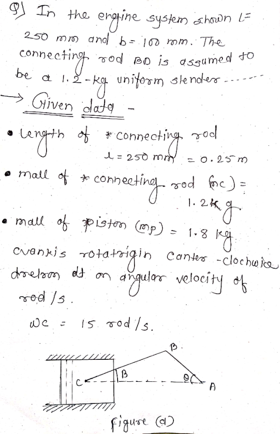
Please show ALL work and answer ALL parts In the engine system shown -250 mm and b 100 mm. The connecting rod BD is assumed to be a 1.2-kg uniform slender rod and is attached to the 1.8-kg piston...
In the en gine system shown, I -160 mm and b- 60 mm. Knowing that the crank AB rotates with a con...
 In the en gine system shown, I -160 mm and b- 60 mm. Knowing that the crank AB rotates with a constant angular velocity of 12 rads/s clockwise. Determine all the reactionary forces as a function of θ and plot these forces as a function of θ At what angle(s) is the reaction force at point D a maxmum? Also, plot the accelerations of the points B and D. The piston has a mass of3 kg, rod BD has mass...
For the engine system of Prob. 15.C3 of Chap. 15, the masses of piston P and the connecting rod B...
 For the engine system of Prob. 15.C3 of Chap. 15, the masses of piston P and the connecting rod BD are 2.5 kg and 3 kg, respectively. Knowing that during a test of the system no force is applied to the face of the piston, use computational software to calculate and plot the horizontal and vertical components of the dynamic reactions exerted on the connecting rod at B and D for values of from 0 to 180° Prob. 15.C3 In...
0 Required information Problem 16.138 General plane motion: System of rigid bodies: Rod and piston DEPENDENT...
 0 Required information Problem 16.138 General plane motion: System of rigid bodies: Rod and piston DEPENDENT MULTI PART PROBLEM - ASSIGN ALL PARTS NOTE: This is a multi-part question. Once an answer is submitted, you will be unable to return to this part. In the engine system shown, /=250 mm and b=100 mm. The connecting rod BD is assumed to be a 1.7-kg uniform slender rod and is attached to the 1.8-kg piston During a test of the system, crank...
Fig. P16.135 and P16.136 150 rad/scounterclockwise, determine (a) the couple M, (b) the components of the...
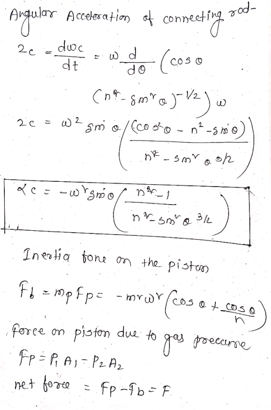
 Fig. P16.135 and P16.136 150 rad/scounterclockwise, determine (a) the couple M, (b) the components of the force exerted at C on rod BC. 16.137 In the engine system shown 1 = 250 mm and b = 100 mm. The connecting rod BD is assumed to be a 1.2-kg uniform slender rod and is attached to the 1.8-kg piston P. During a test of the system, crank AB is made to rotate with a constant angular velocity of 600 rpm clockwise...
Please i need help, show all steps At the instant shown, the uniform 36-kg slender rod...
 Please i need help, show all steps
At the instant shown, the uniform 36-kg slender rod has a counterclockwise angular velocity of W = 6 rad / s. (Figure 1) Part A Determine the tangential component of reaction of pin on the rod at this instant. Express your answer to three significant figures and include the appropriate units. MA ? Value Units Figure < 1 of 1 > Submit Request Answer Part B Determine the normal component of reaction of...
Please i need help, show all steps
At the instant shown, the uniform 36-kg slender rod has a counterclockwise angular velocity of W = 6 rad / s. (Figure 1) Part A Determine the tangential component of reaction of pin on the rod at this instant. Express your answer to three significant figures and include the appropriate units. MA ? Value Units Figure < 1 of 1 > Submit Request Answer Part B Determine the normal component of reaction of...
 In the en gine system shown, I -160 mm and b- 60 mm. Knowing that the crank AB rotates with a constant angular velocity of 12 rads/s clockwise. Determine all the reactionary forces as a function of θ and plot these forces as a function of θ At what angle(s) is the reaction force at point D a maxmum? Also, plot the accelerations of the points B and D. The piston has a mass of3 kg, rod BD has mass...
 For the engine system of Prob. 15.C3 of Chap. 15, the masses of piston P and the connecting rod BD are 2.5 kg and 3 kg, respectively. Knowing that during a test of the system no force is applied to the face of the piston, use computational software to calculate and plot the horizontal and vertical components of the dynamic reactions exerted on the connecting rod at B and D for values of from 0 to 180° Prob. 15.C3 In...
 0 Required information Problem 16.138 General plane motion: System of rigid bodies: Rod and piston DEPENDENT MULTI PART PROBLEM - ASSIGN ALL PARTS NOTE: This is a multi-part question. Once an answer is submitted, you will be unable to return to this part. In the engine system shown, /=250 mm and b=100 mm. The connecting rod BD is assumed to be a 1.7-kg uniform slender rod and is attached to the 1.8-kg piston During a test of the system, crank...
 Fig. P16.135 and P16.136 150 rad/scounterclockwise, determine (a) the couple M, (b) the components of the force exerted at C on rod BC. 16.137 In the engine system shown 1 = 250 mm and b = 100 mm. The connecting rod BD is assumed to be a 1.2-kg uniform slender rod and is attached to the 1.8-kg piston P. During a test of the system, crank AB is made to rotate with a constant angular velocity of 600 rpm clockwise...
 Please i need help, show all steps
At the instant shown, the uniform 36-kg slender rod has a counterclockwise angular velocity of W = 6 rad / s. (Figure 1) Part A Determine the tangential component of reaction of pin on the rod at this instant. Express your answer to three significant figures and include the appropriate units. MA ? Value Units Figure < 1 of 1 > Submit Request Answer Part B Determine the normal component of reaction of...
Please i need help, show all steps
At the instant shown, the uniform 36-kg slender rod has a counterclockwise angular velocity of W = 6 rad / s. (Figure 1) Part A Determine the tangential component of reaction of pin on the rod at this instant. Express your answer to three significant figures and include the appropriate units. MA ? Value Units Figure < 1 of 1 > Submit Request Answer Part B Determine the normal component of reaction of...
Most questions answered within 3 hours.
-
Although Epicurus advocates pursuing pleasure for the
good life, discuss a few reasons why he does...
asked 6 minutes ago -
Problem 1: Present entries to record the selected transactions
described below:
(a)
Issued $2,790,000 of 5-year,...
asked 12 minutes ago -
Using technology to support HR activities increases:
a.
the efficiency of the administrative HR functions.
b....
asked 13 minutes ago -
1. List the features used to classify leaf
types.
2. List some characteristics that are shared...
asked 18 minutes ago -
The three elements of Value Proposition, Key Customers, and
Capabilities operate within an environment. Which of...
asked 20 minutes ago -
Katelynn, a physician, earns $200,000 from her medical practice
in the current year. She receives $45,000...
asked 28 minutes ago -
Each row of the table below describes an aqueous solution at
25°C
.
The second column...
asked 32 minutes ago -
A horizontal wire is at y = 0. Current travels in the +x
direction. The magnetic...
asked 32 minutes ago -
Let X be a continuous random variable whose PDF is Let X be a
continuous random...
asked 54 minutes ago -
Martinez Company’s relevant range of production is 7,500 units
to 12,500 units. When it produces and...
asked 52 minutes ago -
A football with a mass of 1.2 kg is kicked from ground level to
a height...
asked 57 minutes ago -
Remember: Changes in supply determinants shift supply, and
changes in demand determinants shift demand. We say...
asked 56 minutes ago