
![Determine the absolute maximum bending moment about the z-axis in [kNm] Determine the absolute maximum bending moment about t](http://img.homeworklib.com/questions/51cc32c0-89db-11eb-9eb7-b1e850bc79ae.png?x-oss-process=image/resize,w_560)
![Determine the moment of inertia about the y-axis, ly in Determine the maximum compressive stress in the beam in [MPa]. Determ](http://img.homeworklib.com/questions/522cdff0-89db-11eb-ab6b-8f8d7bd0d637.png?x-oss-process=image/resize,w_560)
Homework Answers


Add Answer to:
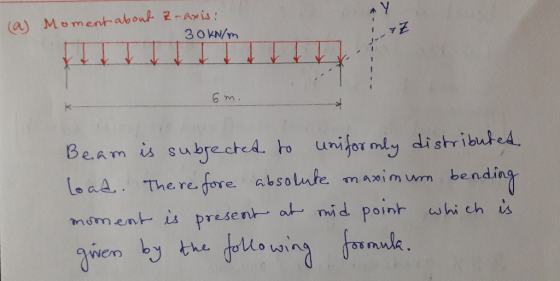
The simply supported beam is subjected to a uniform distributed load, w of 30 kN/m in...
The simply supported beam, with a U cross section, is subjected to a uniformly distributed force...
 The simply supported beam, with a U cross section, is subjected to a uniformly distributed force of 8 kN/m and a concentrated load of 12 kN as shown. (a) Determine the reaction at supports A and B, (b) sketch the shear diagram and the moment diagram, (c) determine the location of the neutral axis of the cross section and calculate its area moment of inertia about the neutral axis, and (d) determine absolute maximum bending stress and (e) absolute maximum...
The beam has the cross-sectional area shown. If the loading intensity o 25 kN/m and the...
 The beam has the cross-sectional area shown. If the loading intensity o 25 kN/m and the length of the beam L is 3 m, answer the questions that follow: 0 TALALRATEATAITTAAAAATTAAAAAL 100 mm 25 mm 25 mm 75 mm 75 mm 25 mm Determine the maximumm bending moment in the bearm in [kNm] Determine the position of the neutral axis, as a distance in [mm] measured from the bottom of the beam i.e. determine V Determine the area moment of...
The beam having a cross-section as shown is subjected to the distributed load w (1) Calculate...
 The beam having a cross-section as shown is subjected to the distributed load w (1) Calculate the moment of inertia, I (2) If the allowable maximum normal stress ơmax-20 MPa, determine the largest distributed load 5. w. (3) If w 1.5 kN/m, determine the maximum bending stress in the beam. Sketch the stress distribution acting over the cross-section. 100 mm 50mm 120 mm 3 m50 mm 3 m
With a U cross section, is subjected to uniformly distributed force 11 kN/m and a concentrated load of 12 kN as shown
 With a U cross section, is subjected to uniformly distributed force 11 kN/m and a concentrated load of 12 kN as shown. (a) the reaction at supports A and B, (b) sketch the shear diagram and the moment diagram, (c) determine the location of neutral axis of the cross section and calculate its area moment of inertia about the neutral axis, and (d) determine absolute maximum bending stress and (e) absolute maximum transverse shear stress.
The simply supported truss is subjected to the central distributed load
 The simply supported truss is subjected to the central distributed load. Neglect the effect of the diagonal lacing and determine the absolute maximum bending stress in the truss The top member is a pipe having an outer diameter of 1 in. and thickness of 3/16 in., and the bottom member is a solid rod having a diameter of 1/2 in.a) Draw the shear and bending moment diagrams for the truss. Identify the maximum shear force and bending moment. b) What is...
A simply supported composite beam 3 m long carries a uniformly distributed load of intensity q= 30 kN/m (see figure)
 A simply supported composite beam 3 m long carries a uniformly distributed load of intensity q= 30 kN/m (see figure). The beam is constructed of a wood member, 100 mm wide by 150 mm deep, and is reinforced on its lower side by a steel plate 8 mm thick and 100 mm wide. (a) Find the maximum bending stresses σw and σs, in the wood and steel, respectively, due to the uniform load if the moduli of elasticity are Ew =...
Figure Q3 shows a simply supported beam carrying a point load. The beam hasa rectangular hollow...
 Figure Q3 shows a simply supported beam carrying a point load. The beam hasa rectangular hollow steel section as shown in Figure Q3. a. Calculate the second moment of area of the section about the horizontal (10 marks) centroidal axis. Calculate the maximum allowable value of the point load Wif the elastic bending (15 marks) b. stress in the beam is to be limited to 250 MPa. c. Calculate the maximum shear stress at q-q in the beam when the...
7.26 Torking stress in either tension or compression is AMS. 92.8 mm x 185.6 mm o MPa. am 3 m long is simply supported at each end and carries a uniformly distributed load of 10 kN/m. The beam...
 7.26
Torking stress in either tension or compression is AMS. 92.8 mm x 185.6 mm o MPa. am 3 m long is simply supported at each end and carries a uniformly distributed load of 10 kN/m. The beam at rectangular cross section, 75 mm x 150 mm. Determine the magnitude and location of the peak bending ress. Also, find the magnitude of the bending stress at a point 25 mm below the upper surface at the section midway betwcen supports....
7.26
Torking stress in either tension or compression is AMS. 92.8 mm x 185.6 mm o MPa. am 3 m long is simply supported at each end and carries a uniformly distributed load of 10 kN/m. The beam at rectangular cross section, 75 mm x 150 mm. Determine the magnitude and location of the peak bending ress. Also, find the magnitude of the bending stress at a point 25 mm below the upper surface at the section midway betwcen supports....
Q2 The 10 m long simply supported beam is subjected to a uniformly distributed load w...
 Q2 The 10 m long simply supported beam is subjected to a uniformly distributed load w = 10 kN/m throughout and a point load P =10 kN at the midspan of the beam, as shown in Figure Q2 (a). The cross section of this beam is depicted in Figure Q2 (b), which consists of three equal rectangular steel members. Self-weight of the beam is neglected. 30 mm P= 10 KN W = 10 kN/m 200 mm 5 m 5 m...
Q2 The 10 m long simply supported beam is subjected to a uniformly distributed load w...
 Q2 The 10 m long simply supported beam is subjected to a uniformly distributed load w = 10 kN/m throughout and a point load P =10 kN at the midspan of the beam, as shown in Figure Q2 (a). The cross section of this beam is depicted in Figure Q2 (b), which consists of three equal rectangular steel members. Self-weight of the beam is neglected. 30 mm P = 10 kN W = 10 kN/m 200 mm 5 m 5...
 The beam has the cross-sectional area shown. If the loading intensity o 25 kN/m and the length of the beam L is 3 m, answer the questions that follow: 0 TALALRATEATAITTAAAAATTAAAAAL 100 mm 25 mm 25 mm 75 mm 75 mm 25 mm Determine the maximumm bending moment in the bearm in [kNm] Determine the position of the neutral axis, as a distance in [mm] measured from the bottom of the beam i.e. determine V Determine the area moment of...
 The beam having a cross-section as shown is subjected to the distributed load w (1) Calculate the moment of inertia, I (2) If the allowable maximum normal stress ơmax-20 MPa, determine the largest distributed load 5. w. (3) If w 1.5 kN/m, determine the maximum bending stress in the beam. Sketch the stress distribution acting over the cross-section. 100 mm 50mm 120 mm 3 m50 mm 3 m
 Figure Q3 shows a simply supported beam carrying a point load. The beam hasa rectangular hollow steel section as shown in Figure Q3. a. Calculate the second moment of area of the section about the horizontal (10 marks) centroidal axis. Calculate the maximum allowable value of the point load Wif the elastic bending (15 marks) b. stress in the beam is to be limited to 250 MPa. c. Calculate the maximum shear stress at q-q in the beam when the...
 7.26
Torking stress in either tension or compression is AMS. 92.8 mm x 185.6 mm o MPa. am 3 m long is simply supported at each end and carries a uniformly distributed load of 10 kN/m. The beam at rectangular cross section, 75 mm x 150 mm. Determine the magnitude and location of the peak bending ress. Also, find the magnitude of the bending stress at a point 25 mm below the upper surface at the section midway betwcen supports....
7.26
Torking stress in either tension or compression is AMS. 92.8 mm x 185.6 mm o MPa. am 3 m long is simply supported at each end and carries a uniformly distributed load of 10 kN/m. The beam at rectangular cross section, 75 mm x 150 mm. Determine the magnitude and location of the peak bending ress. Also, find the magnitude of the bending stress at a point 25 mm below the upper surface at the section midway betwcen supports....
 Q2 The 10 m long simply supported beam is subjected to a uniformly distributed load w = 10 kN/m throughout and a point load P =10 kN at the midspan of the beam, as shown in Figure Q2 (a). The cross section of this beam is depicted in Figure Q2 (b), which consists of three equal rectangular steel members. Self-weight of the beam is neglected. 30 mm P= 10 KN W = 10 kN/m 200 mm 5 m 5 m...
 Q2 The 10 m long simply supported beam is subjected to a uniformly distributed load w = 10 kN/m throughout and a point load P =10 kN at the midspan of the beam, as shown in Figure Q2 (a). The cross section of this beam is depicted in Figure Q2 (b), which consists of three equal rectangular steel members. Self-weight of the beam is neglected. 30 mm P = 10 kN W = 10 kN/m 200 mm 5 m 5...
Most questions answered within 3 hours.
-
1-The Electrons in a beam are moving at 2.7×10⁸ m/s in an
electric field of 15000...
asked 5 minutes ago -
A gas tank is a vertical cylinder. It has a radius of 1m, a
height of...
asked 31 minutes ago -
Accent Software faces the following conditions. All of these
support Accent’s use of a market-penetration pricing...
asked 1 hour ago -
A mathematically inclined friend emails you the following
instructions: "Meet me in the cafeteria the first...
asked 1 hour ago -
A monopoly sells in two countries . The demand curves in the two
countries are p1...
asked 2 hours ago -
A .15kg rubber ball is bounced off a wall. Before hitting the
wall, the ball moves...
asked 3 hours ago -
A manufacturing company preparing to build a new plant is
considering three potential locations for it....
asked 3 hours ago -
B. If compound Y has approximately the same values of solubility
in toluene as compound X,...
asked 3 hours ago -
Oscar Inc. has inventory in Japan valued at 39,051,000 Yen one
year ago. One year ago...
asked 4 hours ago -
If Canada suffered from "fundamental disequilibrium," and its
government choose not to devalue its currency, a...
asked 4 hours ago -
4. How many input & output Key Value Pairs are passed into,
and emitted out of...
asked 4 hours ago -
Why would your heart not function well if constructed of
skeletal muscle? What is the particular...
asked 4 hours ago