
Homework Answers
Add Answer to:
A gear reduction unit uses the countershaft shown in the figure. The solid steel shaft is...
Solve in SI units. A gear reduction unit uses the countershaft shown in the figure. Gear...
 Solve in SI units.
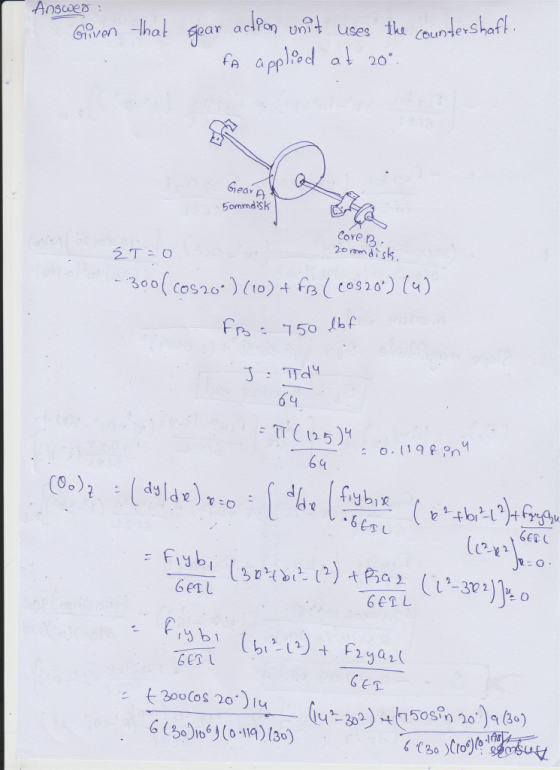
A gear reduction unit uses the countershaft shown in the figure.
Gear A receives power from another gear with the transmitted force
FA applied at the 20ᵒ pressure angle as shown. The power is
transmitted through the shaft and delivered through gear B through
a transmitted force FB at the pressure angle shown. a) Determine
the force FB, assuming the shaft is running at a constant speed. b)
Find the magnitudes of the bearing reaction forces,...
Solve in SI units.
A gear reduction unit uses the countershaft shown in the figure.
Gear A receives power from another gear with the transmitted force
FA applied at the 20ᵒ pressure angle as shown. The power is
transmitted through the shaft and delivered through gear B through
a transmitted force FB at the pressure angle shown. a) Determine
the force FB, assuming the shaft is running at a constant speed. b)
Find the magnitudes of the bearing reaction forces,...
A gear reduction unit uses the countershaft shown A gear A receives power from another gear...
 A gear reduction unit uses the countershaft shown A gear A receives power from another gear with the transmitted force FA applied at the 20° pressure angle as shown. The power is transmitted through the shaft and delivered through gear B through a transmitted force Fa at the pressure angle shown 16 in in in 20° 1.25-in dia (a)Determine the minimum factor of safety for fatigue based on infinite life, using the modified Goodman criterion Gear A 20-in dia. (b)Determine...
Extra Credit) A gear reduction unit uses the countershaft shown in the figure. Gear A receives...
 Extra Credit) A gear reduction unit uses the countershaft shown in the figure. Gear A receives power from another gear with the transmitted force FA applied at the 20° pressure angle as shown. The power is transmitted through the shaft and delivered through gear B through a transmitted force FB at the pressure angle shown. (a) Determine the force FB, assuming the shaft is running at a constant speed. (b) Find the magnitudes of the bearing reaction forces, assuming the...
Q1. Load and Stress Analysis The countershaft with the reverse gears attached to is shown in figu...
 machine design question
Q1. Load and Stress Analysis The countershaft with the reverse gears attached to is shown in figure 2 with the dimension given in table 1. Gear A receives power from another gear with the transmitted force Fa applied at the pressure angle au as shown. The power is transmitted through the shaft and delivered through gear B through a transmitted force Fs at the pressure angle shown. You can find the values of the parameters in table...
machine design question
Q1. Load and Stress Analysis The countershaft with the reverse gears attached to is shown in figure 2 with the dimension given in table 1. Gear A receives power from another gear with the transmitted force Fa applied at the pressure angle au as shown. The power is transmitted through the shaft and delivered through gear B through a transmitted force Fs at the pressure angle shown. You can find the values of the parameters in table...
Open-ended design problem: A gear-reduction unit uses the countershaft overly simplified in the figure below. Propose...
 Open-ended design problem: A gear-reduction unit uses the countershaft overly simplified in the figure below. Propose a detailed 2-D drawing of what the final assembly might look like, including the housing near the bearings, the bearings, the gears, the shaft and the mounting parts as necessary. Note that no sizing is required, just a drawing, that does not need to be to scale. 16 F 25° 240 lbf 96 200 G Gear 3, 24 dia. B Gear 4, 12 dia.
A countershaft carrying two V-belt pulleys is shown in the figure. Pulley A receives power from...
 A countershaft carrying two V-belt pulleys is shown in the figure. Pulley A receives power from a motor through a belt with the belt tensions shown. The power is transmitted through the shaft and delivered to the belt on pulley B. Assume the belt tension on the loose side at Bis 15 percent of the tension on the tight side. For the steel countershaft shown in the figure below, find the slope of the shaft at each bearing. Use superposition...
A countershaft carrying two V-belt pulleys is shown in the figure. Pulley A receives power from...
 A countershaft carrying two V-belt pulleys is shown in the
figure. Pulley A receives power from a motor through a belt with
the belt tensions shown. The power is transmitted through the shaft
and delivered to the belt on pulley B. Assume the belt tension on
the loose side at B is 15 percent of the tension on the tight side.
Yield of the Shaft ?? = 560 ???
a) Determine the tensions in the belt on pulley B, assuming...
A countershaft carrying two V-belt pulleys is shown in the
figure. Pulley A receives power from a motor through a belt with
the belt tensions shown. The power is transmitted through the shaft
and delivered to the belt on pulley B. Assume the belt tension on
the loose side at B is 15 percent of the tension on the tight side.
Yield of the Shaft ?? = 560 ???
a) Determine the tensions in the belt on pulley B, assuming...
11-32 The figure shown is a geared countershaft with an overhanging pinion at C. Select an...
 11-32 The figure shown is a geared countershaft with an overhanging pinion at C. Select an angular- contact ball bearing from Table 11-2 for mounting at O and an 02-series cylindrical roller bearing from Table 11-3 for mounting at B. The force on gear A is FA-600 lbf, and the shaft is to run at a speed of 420 rev/min. Solution of the statics problem gives force of bear- ings against the shaft at O as Ro--387] 467k lbf, and...
Problem 1 (50 points) A countershaft carrying two V-belt pulleys is shown in the figure. Pulley...
 Problem 1 (50 points) A countershaft carrying two V-belt pulleys is shown in the figure. Pulley A receives power from a motor through a belt with tensions shown. The power is transmitted through the shaft and delivered to the belt on pulley B. Assume the belt tension on the loose side at B is 15 percent of the tension on the tight side. 230 mm F: 30-mm dia. 280 mm 300 mm 250-mm dia. 400-mm dia 1000 N 150 N...
(Q6) Figure (3) shows a countershaft with helical gear (B), bevelg (D), and two supporting (Dthe helical par...
 (Q6) Figure (3) shows a countershaft with helical gear (B), bevelg (D), and two supporting (Dthe helical parte n ear \、Q oads acting on the bevel gear are known Forces on the have a ra be determined. Shaft dimensions are known. All shoulder fillets na bearing A takes thrust. The shat rotates at 1000 rpm and is ma iaportant surfaces are finished by grinding. Select suitable radial ball bearings at A and for a dius of 5 mm. Only hardened...
 Solve in SI units.
A gear reduction unit uses the countershaft shown in the figure.
Gear A receives power from another gear with the transmitted force
FA applied at the 20ᵒ pressure angle as shown. The power is
transmitted through the shaft and delivered through gear B through
a transmitted force FB at the pressure angle shown. a) Determine
the force FB, assuming the shaft is running at a constant speed. b)
Find the magnitudes of the bearing reaction forces,...
Solve in SI units.
A gear reduction unit uses the countershaft shown in the figure.
Gear A receives power from another gear with the transmitted force
FA applied at the 20ᵒ pressure angle as shown. The power is
transmitted through the shaft and delivered through gear B through
a transmitted force FB at the pressure angle shown. a) Determine
the force FB, assuming the shaft is running at a constant speed. b)
Find the magnitudes of the bearing reaction forces,...
 A gear reduction unit uses the countershaft shown A gear A receives power from another gear with the transmitted force FA applied at the 20° pressure angle as shown. The power is transmitted through the shaft and delivered through gear B through a transmitted force Fa at the pressure angle shown 16 in in in 20° 1.25-in dia (a)Determine the minimum factor of safety for fatigue based on infinite life, using the modified Goodman criterion Gear A 20-in dia. (b)Determine...
 Extra Credit) A gear reduction unit uses the countershaft shown in the figure. Gear A receives power from another gear with the transmitted force FA applied at the 20° pressure angle as shown. The power is transmitted through the shaft and delivered through gear B through a transmitted force FB at the pressure angle shown. (a) Determine the force FB, assuming the shaft is running at a constant speed. (b) Find the magnitudes of the bearing reaction forces, assuming the...
 machine design question
Q1. Load and Stress Analysis The countershaft with the reverse gears attached to is shown in figure 2 with the dimension given in table 1. Gear A receives power from another gear with the transmitted force Fa applied at the pressure angle au as shown. The power is transmitted through the shaft and delivered through gear B through a transmitted force Fs at the pressure angle shown. You can find the values of the parameters in table...
machine design question
Q1. Load and Stress Analysis The countershaft with the reverse gears attached to is shown in figure 2 with the dimension given in table 1. Gear A receives power from another gear with the transmitted force Fa applied at the pressure angle au as shown. The power is transmitted through the shaft and delivered through gear B through a transmitted force Fs at the pressure angle shown. You can find the values of the parameters in table...
 Open-ended design problem: A gear-reduction unit uses the countershaft overly simplified in the figure below. Propose a detailed 2-D drawing of what the final assembly might look like, including the housing near the bearings, the bearings, the gears, the shaft and the mounting parts as necessary. Note that no sizing is required, just a drawing, that does not need to be to scale. 16 F 25° 240 lbf 96 200 G Gear 3, 24 dia. B Gear 4, 12 dia.
 A countershaft carrying two V-belt pulleys is shown in the figure. Pulley A receives power from a motor through a belt with the belt tensions shown. The power is transmitted through the shaft and delivered to the belt on pulley B. Assume the belt tension on the loose side at Bis 15 percent of the tension on the tight side. For the steel countershaft shown in the figure below, find the slope of the shaft at each bearing. Use superposition...
 A countershaft carrying two V-belt pulleys is shown in the
figure. Pulley A receives power from a motor through a belt with
the belt tensions shown. The power is transmitted through the shaft
and delivered to the belt on pulley B. Assume the belt tension on
the loose side at B is 15 percent of the tension on the tight side.
Yield of the Shaft ?? = 560 ???
a) Determine the tensions in the belt on pulley B, assuming...
A countershaft carrying two V-belt pulleys is shown in the
figure. Pulley A receives power from a motor through a belt with
the belt tensions shown. The power is transmitted through the shaft
and delivered to the belt on pulley B. Assume the belt tension on
the loose side at B is 15 percent of the tension on the tight side.
Yield of the Shaft ?? = 560 ???
a) Determine the tensions in the belt on pulley B, assuming...
 11-32 The figure shown is a geared countershaft with an overhanging pinion at C. Select an angular- contact ball bearing from Table 11-2 for mounting at O and an 02-series cylindrical roller bearing from Table 11-3 for mounting at B. The force on gear A is FA-600 lbf, and the shaft is to run at a speed of 420 rev/min. Solution of the statics problem gives force of bear- ings against the shaft at O as Ro--387] 467k lbf, and...
 Problem 1 (50 points) A countershaft carrying two V-belt pulleys is shown in the figure. Pulley A receives power from a motor through a belt with tensions shown. The power is transmitted through the shaft and delivered to the belt on pulley B. Assume the belt tension on the loose side at B is 15 percent of the tension on the tight side. 230 mm F: 30-mm dia. 280 mm 300 mm 250-mm dia. 400-mm dia 1000 N 150 N...
 (Q6) Figure (3) shows a countershaft with helical gear (B), bevelg (D), and two supporting (Dthe helical parte n ear \、Q oads acting on the bevel gear are known Forces on the have a ra be determined. Shaft dimensions are known. All shoulder fillets na bearing A takes thrust. The shat rotates at 1000 rpm and is ma iaportant surfaces are finished by grinding. Select suitable radial ball bearings at A and for a dius of 5 mm. Only hardened...
Most questions answered within 3 hours.
-
A dragon biologist is setting up an experimental population of
1000 individuals. In dragons, pointy crests...
asked 1 minute ago -
A uniform thin rod of length 0.851 m is hung from a horizontal
nail passing through...
asked 11 minutes ago -
A 747 has a cruising speed of 235 m/s at a height of 10,700
meters. The...
asked 20 minutes ago -
Part 3: Arrows
Write a python program that prompts the user for a number of
columns,...
asked 27 minutes ago -
Need help answering these questions!!
1. What economic concept do you find most interesting in
Macroeconomics?...
asked 31 minutes ago -
1. Nimbus, Inc. produces and sells brooms. This table shows the
relationship between the number of...
asked 35 minutes ago -
A gas occupies 200. mL in a piston. If the pressure of the
piston were decreased...
asked 51 minutes ago -
A fossil is found to have a 14C level of 71.0% compared to
living organisms. How...
asked 55 minutes ago -
Many communist or socialist countries have a department that
addresses public health as well as the...
asked 57 minutes ago -
the following questions are either true or false answers
1. The Central Limit Theorem allows one...
asked 57 minutes ago -
The patient recovery time from a particular surgical procedure
is normally distributed with a mean of...
asked 1 hour ago -
Human relations refer to the way a company arranges people,
jobs, and communications so that work...
asked 1 hour ago