
machine design question
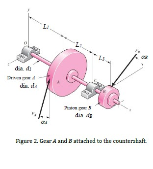
LI し2 し3 CB dia. d Driven gear A dia. du Pinion gear iB dia. dB Figure 2. Gear A and B attached to the countershaft.
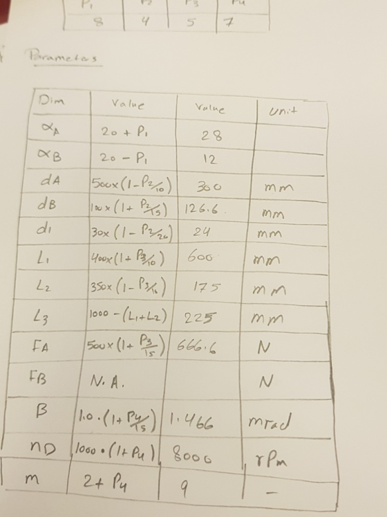
4 Value Vlne 2 8 12 Unit 2 |!。。。..(L' + L.) | 225 1500 × (l+ 은)| 666.4 L9 | mm
Homework Answers
Bending moment, shear force and bending stress all data are
submitted in files below: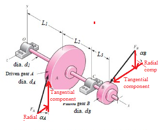


Add Answer to:
Q1. Load and Stress Analysis The countershaft with the reverse gears attached to is shown in figu...
Solve in SI units. A gear reduction unit uses the countershaft shown in the figure. Gear...
 Solve in SI units.
A gear reduction unit uses the countershaft shown in the figure.
Gear A receives power from another gear with the transmitted force
FA applied at the 20ᵒ pressure angle as shown. The power is
transmitted through the shaft and delivered through gear B through
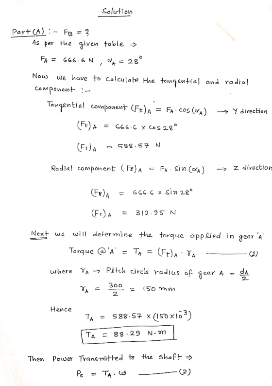
a transmitted force FB at the pressure angle shown. a) Determine
the force FB, assuming the shaft is running at a constant speed. b)
Find the magnitudes of the bearing reaction forces,...
Solve in SI units.
A gear reduction unit uses the countershaft shown in the figure.
Gear A receives power from another gear with the transmitted force
FA applied at the 20ᵒ pressure angle as shown. The power is
transmitted through the shaft and delivered through gear B through
a transmitted force FB at the pressure angle shown. a) Determine
the force FB, assuming the shaft is running at a constant speed. b)
Find the magnitudes of the bearing reaction forces,...
Extra Credit) A gear reduction unit uses the countershaft shown in the figure. Gear A receives...
 Extra Credit) A gear reduction unit uses the countershaft shown in the figure. Gear A receives power from another gear with the transmitted force FA applied at the 20° pressure angle as shown. The power is transmitted through the shaft and delivered through gear B through a transmitted force FB at the pressure angle shown. (a) Determine the force FB, assuming the shaft is running at a constant speed. (b) Find the magnitudes of the bearing reaction forces, assuming the...
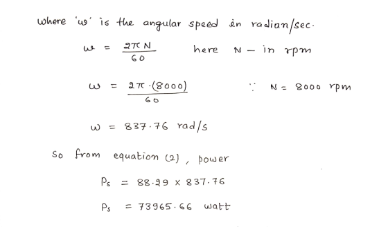
A countershaft carrying two V-belt pulleys is shown in the figure. Pulley A receives power from...
 A countershaft carrying two V-belt pulleys is shown in the
figure. Pulley A receives power from a motor through a belt with
the belt tensions shown. The power is transmitted through the shaft
and delivered to the belt on pulley B. Assume the belt tension on
the loose side at B is 15 percent of the tension on the tight side.
Yield of the Shaft ?? = 560 ???
a) Determine the tensions in the belt on pulley B, assuming...
A countershaft carrying two V-belt pulleys is shown in the
figure. Pulley A receives power from a motor through a belt with
the belt tensions shown. The power is transmitted through the shaft
and delivered to the belt on pulley B. Assume the belt tension on
the loose side at B is 15 percent of the tension on the tight side.
Yield of the Shaft ?? = 560 ???
a) Determine the tensions in the belt on pulley B, assuming...
Problem 2: (Problem 3.79 in the book) A countershaft carrying two V-belt pulleys is shown in...
 Problem 2: (Problem 3.79 in the book) A countershaft carrying two V-belt pulleys is shown in the figure. Pulley A receives power from a motor through a belt with the belt tensions shown. The power is transmitted through the shaft and delivered to the belt on pulley B. Assume the belt tension on the loose side at B is 15 percent of the tension on the tight side. (a) Determine the tensions in the belt on pulley B, assuming the...
A gear reduction unit uses the countershaft shown A gear A receives power from another gear...
 A gear reduction unit uses the countershaft shown A gear A receives power from another gear with the transmitted force FA applied at the 20° pressure angle as shown. The power is transmitted through the shaft and delivered through gear B through a transmitted force Fa at the pressure angle shown 16 in in in 20° 1.25-in dia (a)Determine the minimum factor of safety for fatigue based on infinite life, using the modified Goodman criterion Gear A 20-in dia. (b)Determine...
6 dia 300 Ibf 50 lbf T. . 1 dia 8 dia A countershaft carrying two...
 6 dia 300 Ibf 50 lbf T. . 1 dia 8 dia A countershaft carrying two V-belt pulleys is shown in the figure. Pulley A receives power from a motor through a belt with the belt tension shown. The power is transmitted through the shaft and delivered to the belt on pulley B. Assume the belt tension on the loose side at B is 15% of the tension on the tight side. 3. (5) Determine the tensions in the belt...
A gear reduction unit uses the countershaft shown in the figure. The solid steel shaft is...
 A gear reduction unit uses the countershaft shown in the figure. The solid steel shaft is simply supported by bearings at points O and C. Gear A receives power from another gear with the transmitted force FA applied at the 200 pressure angle as shown. The power is transmitted through the shaft and delivered through gear B through a transmitted force Fa at the pressure angle shown. 0 350 mm 225 ma Gear A 500-mm dia Gear B 200 mm...
I. The countershaft shown in the Fig Q1 has two spur gears mounted on it with teeth cut wi a 20 pressure angle....
 I. The countershaft shown in the Fig Q1 has two spur gears mounted on it with teeth cut wi a 20 pressure angle. The shaft (grooved) is to be made of cold-drawn AISI 1040 steel havin Sut 779 MPa and S,-593 MPa, an elongation of 19% and HB-262. You are asked to size the shaft for safe operation according to DE-Elliptic criterion by using a factor of safety of 2.5 and a reliability of 99 percent. The stress-concentration factors for...
A countershaft carrying two V-belt pulleys is shown in figure 1 (dimensions in inches). Pulley A...
 A countershaft carrying two
V-belt pulleys is shown in figure 1 (dimensions in inches). Pulley
A receives power from a motor through a belt with the belt tensions
shown. The power is transmitted through the shaft and delivered to
the belt on pulley B. Assume the belt tension on the loose side at
B is
15 percent of the tension on the tight side.
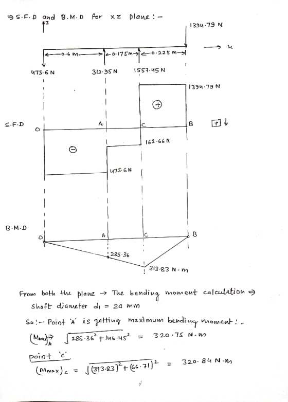
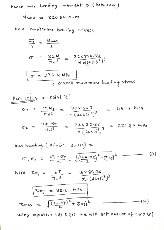
a) At the point of maximum bending moment, determine the principal
stresses and the maximum shear...
A countershaft carrying two
V-belt pulleys is shown in figure 1 (dimensions in inches). Pulley
A receives power from a motor through a belt with the belt tensions
shown. The power is transmitted through the shaft and delivered to
the belt on pulley B. Assume the belt tension on the loose side at
B is
15 percent of the tension on the tight side.
a) At the point of maximum bending moment, determine the principal
stresses and the maximum shear...
1. The countershaft shown in the Fig QI has two spur gears mounted on it with teeth cut with a 20 pressure angle...
 1. The countershaft shown in the Fig QI has two spur gears mounted on it with teeth cut with a 20 pressure angle. The shaft (grooved) is to be made of cold-drawn AISI 1040 steel having Sut= 779 MPa and S,-593 MPa, an elongation of 19% and HB-262. You are asked to size the shaft for safe operation according to DE-Eilliptic criterion by using a factor of safety of 2.5 and a reliability of 99 percent. The stress-concentration factors for...
 Solve in SI units.
A gear reduction unit uses the countershaft shown in the figure.
Gear A receives power from another gear with the transmitted force
FA applied at the 20ᵒ pressure angle as shown. The power is
transmitted through the shaft and delivered through gear B through
a transmitted force FB at the pressure angle shown. a) Determine
the force FB, assuming the shaft is running at a constant speed. b)
Find the magnitudes of the bearing reaction forces,...
Solve in SI units.
A gear reduction unit uses the countershaft shown in the figure.
Gear A receives power from another gear with the transmitted force
FA applied at the 20ᵒ pressure angle as shown. The power is
transmitted through the shaft and delivered through gear B through
a transmitted force FB at the pressure angle shown. a) Determine
the force FB, assuming the shaft is running at a constant speed. b)
Find the magnitudes of the bearing reaction forces,...
 Extra Credit) A gear reduction unit uses the countershaft shown in the figure. Gear A receives power from another gear with the transmitted force FA applied at the 20° pressure angle as shown. The power is transmitted through the shaft and delivered through gear B through a transmitted force FB at the pressure angle shown. (a) Determine the force FB, assuming the shaft is running at a constant speed. (b) Find the magnitudes of the bearing reaction forces, assuming the...
 A countershaft carrying two V-belt pulleys is shown in the
figure. Pulley A receives power from a motor through a belt with
the belt tensions shown. The power is transmitted through the shaft
and delivered to the belt on pulley B. Assume the belt tension on
the loose side at B is 15 percent of the tension on the tight side.
Yield of the Shaft ?? = 560 ???
a) Determine the tensions in the belt on pulley B, assuming...
A countershaft carrying two V-belt pulleys is shown in the
figure. Pulley A receives power from a motor through a belt with
the belt tensions shown. The power is transmitted through the shaft
and delivered to the belt on pulley B. Assume the belt tension on
the loose side at B is 15 percent of the tension on the tight side.
Yield of the Shaft ?? = 560 ???
a) Determine the tensions in the belt on pulley B, assuming...
 Problem 2: (Problem 3.79 in the book) A countershaft carrying two V-belt pulleys is shown in the figure. Pulley A receives power from a motor through a belt with the belt tensions shown. The power is transmitted through the shaft and delivered to the belt on pulley B. Assume the belt tension on the loose side at B is 15 percent of the tension on the tight side. (a) Determine the tensions in the belt on pulley B, assuming the...
 A gear reduction unit uses the countershaft shown A gear A receives power from another gear with the transmitted force FA applied at the 20° pressure angle as shown. The power is transmitted through the shaft and delivered through gear B through a transmitted force Fa at the pressure angle shown 16 in in in 20° 1.25-in dia (a)Determine the minimum factor of safety for fatigue based on infinite life, using the modified Goodman criterion Gear A 20-in dia. (b)Determine...
 6 dia 300 Ibf 50 lbf T. . 1 dia 8 dia A countershaft carrying two V-belt pulleys is shown in the figure. Pulley A receives power from a motor through a belt with the belt tension shown. The power is transmitted through the shaft and delivered to the belt on pulley B. Assume the belt tension on the loose side at B is 15% of the tension on the tight side. 3. (5) Determine the tensions in the belt...
 A gear reduction unit uses the countershaft shown in the figure. The solid steel shaft is simply supported by bearings at points O and C. Gear A receives power from another gear with the transmitted force FA applied at the 200 pressure angle as shown. The power is transmitted through the shaft and delivered through gear B through a transmitted force Fa at the pressure angle shown. 0 350 mm 225 ma Gear A 500-mm dia Gear B 200 mm...
 I. The countershaft shown in the Fig Q1 has two spur gears mounted on it with teeth cut wi a 20 pressure angle. The shaft (grooved) is to be made of cold-drawn AISI 1040 steel havin Sut 779 MPa and S,-593 MPa, an elongation of 19% and HB-262. You are asked to size the shaft for safe operation according to DE-Elliptic criterion by using a factor of safety of 2.5 and a reliability of 99 percent. The stress-concentration factors for...
 A countershaft carrying two
V-belt pulleys is shown in figure 1 (dimensions in inches). Pulley
A receives power from a motor through a belt with the belt tensions
shown. The power is transmitted through the shaft and delivered to
the belt on pulley B. Assume the belt tension on the loose side at
B is
15 percent of the tension on the tight side.
a) At the point of maximum bending moment, determine the principal
stresses and the maximum shear...
A countershaft carrying two
V-belt pulleys is shown in figure 1 (dimensions in inches). Pulley
A receives power from a motor through a belt with the belt tensions
shown. The power is transmitted through the shaft and delivered to
the belt on pulley B. Assume the belt tension on the loose side at
B is
15 percent of the tension on the tight side.
a) At the point of maximum bending moment, determine the principal
stresses and the maximum shear...
 1. The countershaft shown in the Fig QI has two spur gears mounted on it with teeth cut with a 20 pressure angle. The shaft (grooved) is to be made of cold-drawn AISI 1040 steel having Sut= 779 MPa and S,-593 MPa, an elongation of 19% and HB-262. You are asked to size the shaft for safe operation according to DE-Eilliptic criterion by using a factor of safety of 2.5 and a reliability of 99 percent. The stress-concentration factors for...
Most questions answered within 3 hours.
-
Please help!!
Histidine is a polyprotic acid.
1. Draw a complete titration curve assuming 10.0 mL...
asked 1 minute from now -
How do I write a C program called binary that takes a single
command line argument,...
asked 1 minute from now -
assume the salaries of elementary school teachers in the United
States normally distributed with a mean...
asked 1 minute ago -
Question 10 - According to the Chapter Perspective, anti-hugging
policies have done which of the following?...
asked 4 minutes ago -
Research and explain how a hobby servo motor uses the pulse
width of the control signal...
asked 8 minutes ago -
To construct a solenoid, you wrap insulated wire uniformly
around a plastic tube 14 cm in...
asked 22 minutes ago -
Using traditional methods it takes 11.4 hours to receive a basic
driving license. A new license...
asked 27 minutes ago -
From the Principle of Conservation of Linear Moment, obtain the
Cauchy Movement equations in the Eulerian...
asked 39 minutes ago -
A
solution is made by disolving 2.54 mg of sodium benzoate in 75.00
kg H20
a)...
asked 45 minutes ago -
Sketch the crystal field splitting diagram for the low-spin
[Fe(CN)6 ] 4 - ion.
asked 47 minutes ago -
Sketch the homonuclear diatomic MO diagram for
Mo22+. What kind of magnetism does this dimer
exhibit?
asked 1 hour ago -
Consider a situation where current output (real GDP) is
currently below potential GDP. What type of...
asked 1 hour ago