

Homework Answers
Add Answer to:
Extra Credit) A gear reduction unit uses the countershaft shown in the figure. Gear A receives...
Solve in SI units. A gear reduction unit uses the countershaft shown in the figure. Gear...
 Solve in SI units.
A gear reduction unit uses the countershaft shown in the figure.
Gear A receives power from another gear with the transmitted force
FA applied at the 20ᵒ pressure angle as shown. The power is
transmitted through the shaft and delivered through gear B through
a transmitted force FB at the pressure angle shown. a) Determine
the force FB, assuming the shaft is running at a constant speed. b)
Find the magnitudes of the bearing reaction forces,...
Solve in SI units.
A gear reduction unit uses the countershaft shown in the figure.
Gear A receives power from another gear with the transmitted force
FA applied at the 20ᵒ pressure angle as shown. The power is
transmitted through the shaft and delivered through gear B through
a transmitted force FB at the pressure angle shown. a) Determine
the force FB, assuming the shaft is running at a constant speed. b)
Find the magnitudes of the bearing reaction forces,...
Q1. Load and Stress Analysis The countershaft with the reverse gears attached to is shown in figu...
 machine design question
Q1. Load and Stress Analysis The countershaft with the reverse gears attached to is shown in figure 2 with the dimension given in table 1. Gear A receives power from another gear with the transmitted force Fa applied at the pressure angle au as shown. The power is transmitted through the shaft and delivered through gear B through a transmitted force Fs at the pressure angle shown. You can find the values of the parameters in table...
machine design question
Q1. Load and Stress Analysis The countershaft with the reverse gears attached to is shown in figure 2 with the dimension given in table 1. Gear A receives power from another gear with the transmitted force Fa applied at the pressure angle au as shown. The power is transmitted through the shaft and delivered through gear B through a transmitted force Fs at the pressure angle shown. You can find the values of the parameters in table...
A countershaft carrying two V-belt pulleys is shown in the figure. Pulley A receives power from...
 A countershaft carrying two V-belt pulleys is shown in the
figure. Pulley A receives power from a motor through a belt with
the belt tensions shown. The power is transmitted through the shaft
and delivered to the belt on pulley B. Assume the belt tension on
the loose side at B is 15 percent of the tension on the tight side.
Yield of the Shaft ?? = 560 ???
a) Determine the tensions in the belt on pulley B, assuming...
A countershaft carrying two V-belt pulleys is shown in the
figure. Pulley A receives power from a motor through a belt with
the belt tensions shown. The power is transmitted through the shaft
and delivered to the belt on pulley B. Assume the belt tension on
the loose side at B is 15 percent of the tension on the tight side.
Yield of the Shaft ?? = 560 ???
a) Determine the tensions in the belt on pulley B, assuming...
A gear reduction unit uses the countershaft shown A gear A receives power from another gear...
 A gear reduction unit uses the countershaft shown A gear A receives power from another gear with the transmitted force FA applied at the 20° pressure angle as shown. The power is transmitted through the shaft and delivered through gear B through a transmitted force Fa at the pressure angle shown 16 in in in 20° 1.25-in dia (a)Determine the minimum factor of safety for fatigue based on infinite life, using the modified Goodman criterion Gear A 20-in dia. (b)Determine...
Problem 2: (Problem 3.79 in the book) A countershaft carrying two V-belt pulleys is shown in...
 Problem 2: (Problem 3.79 in the book) A countershaft carrying two V-belt pulleys is shown in the figure. Pulley A receives power from a motor through a belt with the belt tensions shown. The power is transmitted through the shaft and delivered to the belt on pulley B. Assume the belt tension on the loose side at B is 15 percent of the tension on the tight side. (a) Determine the tensions in the belt on pulley B, assuming the...
A gear reduction unit uses the countershaft shown in the figure. The solid steel shaft is...
 A gear reduction unit uses the countershaft shown in the figure. The solid steel shaft is simply supported by bearings at points O and C. Gear A receives power from another gear with the transmitted force FA applied at the 200 pressure angle as shown. The power is transmitted through the shaft and delivered through gear B through a transmitted force Fa at the pressure angle shown. 0 350 mm 225 ma Gear A 500-mm dia Gear B 200 mm...
6 dia 300 Ibf 50 lbf T. . 1 dia 8 dia A countershaft carrying two...
 6 dia 300 Ibf 50 lbf T. . 1 dia 8 dia A countershaft carrying two V-belt pulleys is shown in the figure. Pulley A receives power from a motor through a belt with the belt tension shown. The power is transmitted through the shaft and delivered to the belt on pulley B. Assume the belt tension on the loose side at B is 15% of the tension on the tight side. 3. (5) Determine the tensions in the belt...
A countershaft carrying two V-belt pulleys is shown in figure 1 (dimensions in inches). Pulley A...
 A countershaft carrying two
V-belt pulleys is shown in figure 1 (dimensions in inches). Pulley
A receives power from a motor through a belt with the belt tensions
shown. The power is transmitted through the shaft and delivered to
the belt on pulley B. Assume the belt tension on the loose side at
B is
15 percent of the tension on the tight side.
a) At the point of maximum bending moment, determine the principal
stresses and the maximum shear...
A countershaft carrying two
V-belt pulleys is shown in figure 1 (dimensions in inches). Pulley
A receives power from a motor through a belt with the belt tensions
shown. The power is transmitted through the shaft and delivered to
the belt on pulley B. Assume the belt tension on the loose side at
B is
15 percent of the tension on the tight side.
a) At the point of maximum bending moment, determine the principal
stresses and the maximum shear...
Figure 1 shows the layout of countershaft used to transmit power to a blower through a...
 Figure 1 shows the layout of countershaft used to transmit power to a blower through a pulley drive (4-5). Pulley (driving sheave) 4 has a diameter of 125-mm and pulley (driven sheave) 5 has a diameter of 75 mm. Pulley 5 is mounted vertically below pulley 4 (as shown in the figure). Belt tension on the loose side is 20% of the tension on the tight side. A power of 7.5 kW is transmitted via the gear set (2-3) from...
PLEASE CAN YOU SOLVE THE HOMEWORK ACCORDING TO THE ITEMS AND BY STATING WHICH ITEM THE...
 PLEASE CAN YOU SOLVE THE HOMEWORK ACCORDING TO THE ITEMS AND BY
STATING WHICH ITEM THE ANSWERS BELONG TO?
THE ANSWER IS EXPECTED AS SOON AS POSSIBLE
EMEGENCY HOMEWORK
The shaft EFG, which is running at constant speed of n (rev/min) and transmitting a power of P (kW), contains gear F. Gear F transmits torque to shaft ABCD through gear C, which drives the chain sprocket at B, transmitting a force P as shown. Sprocket B, gear C, and gear...
PLEASE CAN YOU SOLVE THE HOMEWORK ACCORDING TO THE ITEMS AND BY
STATING WHICH ITEM THE ANSWERS BELONG TO?
THE ANSWER IS EXPECTED AS SOON AS POSSIBLE
EMEGENCY HOMEWORK
The shaft EFG, which is running at constant speed of n (rev/min) and transmitting a power of P (kW), contains gear F. Gear F transmits torque to shaft ABCD through gear C, which drives the chain sprocket at B, transmitting a force P as shown. Sprocket B, gear C, and gear...
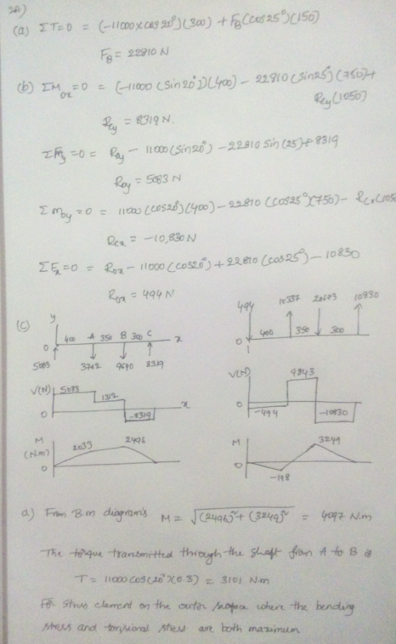
 Solve in SI units.
A gear reduction unit uses the countershaft shown in the figure.
Gear A receives power from another gear with the transmitted force
FA applied at the 20ᵒ pressure angle as shown. The power is
transmitted through the shaft and delivered through gear B through
a transmitted force FB at the pressure angle shown. a) Determine
the force FB, assuming the shaft is running at a constant speed. b)
Find the magnitudes of the bearing reaction forces,...
Solve in SI units.
A gear reduction unit uses the countershaft shown in the figure.
Gear A receives power from another gear with the transmitted force
FA applied at the 20ᵒ pressure angle as shown. The power is
transmitted through the shaft and delivered through gear B through
a transmitted force FB at the pressure angle shown. a) Determine
the force FB, assuming the shaft is running at a constant speed. b)
Find the magnitudes of the bearing reaction forces,...
 machine design question
Q1. Load and Stress Analysis The countershaft with the reverse gears attached to is shown in figure 2 with the dimension given in table 1. Gear A receives power from another gear with the transmitted force Fa applied at the pressure angle au as shown. The power is transmitted through the shaft and delivered through gear B through a transmitted force Fs at the pressure angle shown. You can find the values of the parameters in table...
machine design question
Q1. Load and Stress Analysis The countershaft with the reverse gears attached to is shown in figure 2 with the dimension given in table 1. Gear A receives power from another gear with the transmitted force Fa applied at the pressure angle au as shown. The power is transmitted through the shaft and delivered through gear B through a transmitted force Fs at the pressure angle shown. You can find the values of the parameters in table...
 A countershaft carrying two V-belt pulleys is shown in the
figure. Pulley A receives power from a motor through a belt with
the belt tensions shown. The power is transmitted through the shaft
and delivered to the belt on pulley B. Assume the belt tension on
the loose side at B is 15 percent of the tension on the tight side.
Yield of the Shaft ?? = 560 ???
a) Determine the tensions in the belt on pulley B, assuming...
A countershaft carrying two V-belt pulleys is shown in the
figure. Pulley A receives power from a motor through a belt with
the belt tensions shown. The power is transmitted through the shaft
and delivered to the belt on pulley B. Assume the belt tension on
the loose side at B is 15 percent of the tension on the tight side.
Yield of the Shaft ?? = 560 ???
a) Determine the tensions in the belt on pulley B, assuming...
 A gear reduction unit uses the countershaft shown A gear A receives power from another gear with the transmitted force FA applied at the 20° pressure angle as shown. The power is transmitted through the shaft and delivered through gear B through a transmitted force Fa at the pressure angle shown 16 in in in 20° 1.25-in dia (a)Determine the minimum factor of safety for fatigue based on infinite life, using the modified Goodman criterion Gear A 20-in dia. (b)Determine...
 Problem 2: (Problem 3.79 in the book) A countershaft carrying two V-belt pulleys is shown in the figure. Pulley A receives power from a motor through a belt with the belt tensions shown. The power is transmitted through the shaft and delivered to the belt on pulley B. Assume the belt tension on the loose side at B is 15 percent of the tension on the tight side. (a) Determine the tensions in the belt on pulley B, assuming the...
 A gear reduction unit uses the countershaft shown in the figure. The solid steel shaft is simply supported by bearings at points O and C. Gear A receives power from another gear with the transmitted force FA applied at the 200 pressure angle as shown. The power is transmitted through the shaft and delivered through gear B through a transmitted force Fa at the pressure angle shown. 0 350 mm 225 ma Gear A 500-mm dia Gear B 200 mm...
 6 dia 300 Ibf 50 lbf T. . 1 dia 8 dia A countershaft carrying two V-belt pulleys is shown in the figure. Pulley A receives power from a motor through a belt with the belt tension shown. The power is transmitted through the shaft and delivered to the belt on pulley B. Assume the belt tension on the loose side at B is 15% of the tension on the tight side. 3. (5) Determine the tensions in the belt...
 A countershaft carrying two
V-belt pulleys is shown in figure 1 (dimensions in inches). Pulley
A receives power from a motor through a belt with the belt tensions
shown. The power is transmitted through the shaft and delivered to
the belt on pulley B. Assume the belt tension on the loose side at
B is
15 percent of the tension on the tight side.
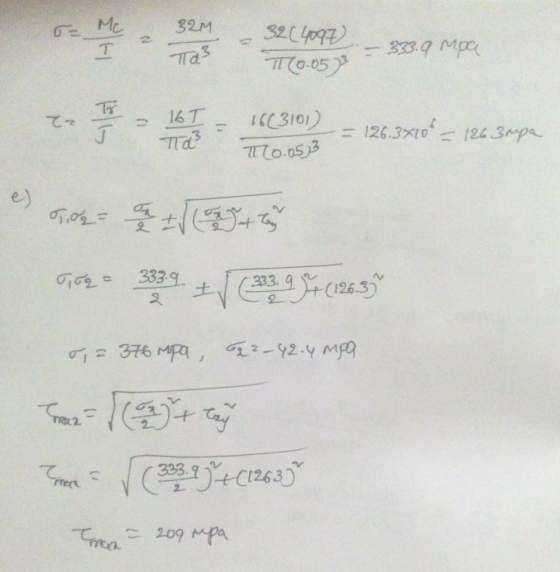
a) At the point of maximum bending moment, determine the principal
stresses and the maximum shear...
A countershaft carrying two
V-belt pulleys is shown in figure 1 (dimensions in inches). Pulley
A receives power from a motor through a belt with the belt tensions
shown. The power is transmitted through the shaft and delivered to
the belt on pulley B. Assume the belt tension on the loose side at
B is
15 percent of the tension on the tight side.
a) At the point of maximum bending moment, determine the principal
stresses and the maximum shear...
 Figure 1 shows the layout of countershaft used to transmit power to a blower through a pulley drive (4-5). Pulley (driving sheave) 4 has a diameter of 125-mm and pulley (driven sheave) 5 has a diameter of 75 mm. Pulley 5 is mounted vertically below pulley 4 (as shown in the figure). Belt tension on the loose side is 20% of the tension on the tight side. A power of 7.5 kW is transmitted via the gear set (2-3) from...
 PLEASE CAN YOU SOLVE THE HOMEWORK ACCORDING TO THE ITEMS AND BY
STATING WHICH ITEM THE ANSWERS BELONG TO?
THE ANSWER IS EXPECTED AS SOON AS POSSIBLE
EMEGENCY HOMEWORK
The shaft EFG, which is running at constant speed of n (rev/min) and transmitting a power of P (kW), contains gear F. Gear F transmits torque to shaft ABCD through gear C, which drives the chain sprocket at B, transmitting a force P as shown. Sprocket B, gear C, and gear...
PLEASE CAN YOU SOLVE THE HOMEWORK ACCORDING TO THE ITEMS AND BY
STATING WHICH ITEM THE ANSWERS BELONG TO?
THE ANSWER IS EXPECTED AS SOON AS POSSIBLE
EMEGENCY HOMEWORK
The shaft EFG, which is running at constant speed of n (rev/min) and transmitting a power of P (kW), contains gear F. Gear F transmits torque to shaft ABCD through gear C, which drives the chain sprocket at B, transmitting a force P as shown. Sprocket B, gear C, and gear...
Most questions answered within 3 hours.
-
You and your opponent both roll a fair die. If you both roll the
same number,...
asked 6 minutes ago -
In a study of the accuracy of fast food drive-through orders,
Restaurant A had 257 accurate...
asked 6 minutes ago -
Identify and describe in detail the four categories of
institutions that could be included in a...
asked 12 minutes ago -
In python
class Customer:
def __init__(self, customer_id, last_name, first_name, phone_number, address):
self._customer_id = int(customer_id)
self._last_name =...
asked 19 minutes ago -
What is an example of a limitation in implementing a new
ERP system and how it...
asked 14 minutes ago -
In a section of 9.7cm of an artery with a radius of 2.6mm there
is a...
asked 15 minutes ago -
the two carboxylic acid groups of aspartic acid have different
acidities with pKa values of 2.1...
asked 19 minutes ago -
Would CuCO3 aqueous salt combined with calcium chloride
form a solid precipitate? If so, what would...
asked 18 minutes ago -
How do ECM Solutions assist in embedding a culture of continuous
improvement in an organization? (Project...
asked 39 minutes ago -
Directions
These directions introduce the idea of Essential Questions.
Since this may be a new concept...
asked 41 minutes ago -
1.b. Fiscal policy is said to suffer from ‘crowding out’.
Explain what this means and why...
asked 58 minutes ago -
The equation for the reaction of nitrogen and oxygen to form
nitrogen oxide is written as...
asked 1 hour ago