
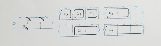
![[5] Write down the KVL expressions in terms of Vs, V1, V2, V3, V4, Vs, and Vo for each of the six loops, La, LB, Lc, Lp, LE,](http://img.homeworklib.com/questions/ad22fba0-8b59-11eb-bd4f-7572074e6005.png?x-oss-process=image/resize,w_560)
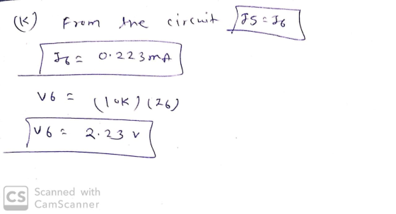
![17] With the equivalent resistance, calculate the current Is or II (same currents) flowing through the 15V source, Vs. Now us](http://img.homeworklib.com/questions/af721af0-8b59-11eb-b37d-e9d559e8a7ac.png?x-oss-process=image/resize,w_560)
I need help to know how to solve 5) and 7)
please explain how to solve. thank you
Homework Answers
![1 2 ] 132K 7 161 ok Ju fokusok ovo Tias LA- K10 | Tч L 114 9:56 From LA Luup VS -VI-V 2.20 Jus: vi tuz From LB Loup tot V2 +](http://img.homeworklib.com/questions/d0767640-8b59-11eb-ac31-81872f3af8d0.png?x-oss-process=image/resize,w_560)

![VS - 5K (35) 20 Is is a 135= 54 = 3mA (n=103) Now (1) Vis (2K) 31 VE 6 v ] (c) From LA Lap VSE VA tv2 V2 = 15-6 [v2=gv] (d) 3](http://img.homeworklib.com/questions/d41867d0-8b59-11eb-955a-9984661bae83.png?x-oss-process=image/resize,w_560)

Add Answer to:
I need help to know how to solve 5) and 7)
please explain how to solve....
PLEASE HELP! Jan. 31, 2018 Name: Section: I. Consider the circuit shown in figure (a) Write...
 PLEASE HELP!
Jan. 31, 2018 Name: Section: I. Consider the circuit shown in figure (a) Write the mesh-current equations (b) Write the for the circuit. D。~of SOL the circuit DO NOT SOLVE shown in figure 2. The sinusoidal source is the circuit to the frequency domain er the circuit (a) Transto with the mesh-current method to find thement (b) Use phasors with the mesh (c) Find the average power absorbed source is 、dt) = 2 sin (100t + 90") volts....
PLEASE HELP!
Jan. 31, 2018 Name: Section: I. Consider the circuit shown in figure (a) Write the mesh-current equations (b) Write the for the circuit. D。~of SOL the circuit DO NOT SOLVE shown in figure 2. The sinusoidal source is the circuit to the frequency domain er the circuit (a) Transto with the mesh-current method to find thement (b) Use phasors with the mesh (c) Find the average power absorbed source is 、dt) = 2 sin (100t + 90") volts....
Need help using KVL to verify 3 loops and that KCL holds at each node! Thank...
 Need help using KVL to verify 3 loops and that KCL holds at
each node! Thank you!
1ΚΩ 4.7ΚΩ I2 I + 4 10, 13 2.7KΩ 13 ° 3.3ΚΩ 2.7KΩ 1ΚΩ ΟΙ - V6 6 - V5 Figure 1.8 6. Construct the circuit of Figure 1.8. Measure each of the variables listed in Table 1.7, and calculate the % error for each. Verify that KVL holds for each of the 3 loops in the circuit. Verify that KCL holds at...
Need help using KVL to verify 3 loops and that KCL holds at
each node! Thank you!
1ΚΩ 4.7ΚΩ I2 I + 4 10, 13 2.7KΩ 13 ° 3.3ΚΩ 2.7KΩ 1ΚΩ ΟΙ - V6 6 - V5 Figure 1.8 6. Construct the circuit of Figure 1.8. Measure each of the variables listed in Table 1.7, and calculate the % error for each. Verify that KVL holds for each of the 3 loops in the circuit. Verify that KCL holds at...
i dont undersrand how to calculate the values from measured data? 2. Turn on the DC...
 i dont undersrand how to calculate the values from measured
data?
2. Turn on the DC power supply, measure its output voltage with DMM2 and record it as measured data Vs in Table 6. 3. Use DMM2 to measure the voltages V, V2.V. Va across R R. RR respectively. Use DMMI to measure the current Is (notice: Is=1= 12 + 1,-1). Record the measured values of I, and V., V2, V3. V4 in Table 6. 4. Turn off the DC...
i dont undersrand how to calculate the values from measured
data?
2. Turn on the DC power supply, measure its output voltage with DMM2 and record it as measured data Vs in Table 6. 3. Use DMM2 to measure the voltages V, V2.V. Va across R R. RR respectively. Use DMMI to measure the current Is (notice: Is=1= 12 + 1,-1). Record the measured values of I, and V., V2, V3. V4 in Table 6. 4. Turn off the DC...
Problemuǐ(30 points) Consider the circuit in Figure 1 1Ω 4A Figure I. DC resistive circuit Submit...
 Problemuǐ(30 points) Consider the circuit in Figure 1 1Ω 4A Figure I. DC resistive circuit Submit these Numerical Values in the Answer Sheet 5 points:IA 5 points: IA 5 points:VV 5 points: V.V 5 points : Power of the 2 Ω resistor Li 5 points: Power of the current source [W 1.a : Use KCL, KVL, and Ohm's Law to calculate 1 [AJ. I2 IA]. V1 IV] and V2 [V] 工 20-120 A 112 2. L.b: Verify your results by...
Learning Goal: To use the node-voltage method to solve circuits that contain resistors and independent sources....
 Learning Goal: To use the node-voltage method to solve circuits that contain resistors and independent sources. The node-voltage method is a general technique for solving circuits. Fundamentally, it involves writing KCL equations at essential nodes. You should review KCL and the definition of an essential node before beginning. In this tutorial, you will use the node-voltage method to find the current through the voltage source, io , and the voltage drop across the 5 kN resistor, vo, for the circuit...
Name: Section: Jan. 31, 2018 1. Consider the circuit shown in figure 1 (a) Write the...
 Name: Section: Jan. 31, 2018 1. Consider the circuit shown in figure 1 (a) Write the mesh-current equations for the circuit. DO NOT SOLVE. (b) Write the node.voltage equations for the cireuit. DO NOT SOLVE 2. Consider the circuit shown in figure 2. The sinusoidal source is v,(04 sin (100t+90) volts (a) Transform the circuit to the frequency domain. (b) Use phasors with the mesh-current method to find the steady state expression for i(t). (c) Find the average power absorbed...
please solve them all 2) For the circuit shown in Figure 1. Find the following: A....
 please solve them all
2) For the circuit shown in Figure 1. Find the following: A. How many independent loops are present in the circuit? B. How many nodes are present in the circuit? C. Write a KVL equation at every independent loop (mesh) in the circuit in terms of the indicated voltage and current variables. D. Write a KCL equation at every node in the circuit. Write those equations using the indicated voltage variables by incorporating Ohm's Law for...
please solve them all
2) For the circuit shown in Figure 1. Find the following: A. How many independent loops are present in the circuit? B. How many nodes are present in the circuit? C. Write a KVL equation at every independent loop (mesh) in the circuit in terms of the indicated voltage and current variables. D. Write a KCL equation at every node in the circuit. Write those equations using the indicated voltage variables by incorporating Ohm's Law for...
Learning Goal: To use the node-voltage method to solve circuits with branches containing only a voltage...
 Learning Goal: To use the node-voltage method to solve circuits with branches containing only a voltage source. The node-voltage method is a general technique for solving circuits. Fundamentally, it involves writing KCL equations at essential nodes. When the circuit contains a dependent source, you must write a constraint equation for each dependent source, in addition to the KCL equations. When the circuit contains one or more voltage sources that are the only components in branches connecting two essential nodes, the...
ri R$ 7:) Here, each V represents a change in voltage (in volts) at a battery,...
 ri R$ 7:) Here, each V represents a change in voltage (in volts) at a battery, each R represents a resistance (in ohms) at a resistor and each I represents a current (in amps) through a wire. These quantities obey two simple laws: 1. Ohm's law: The voltage drop across a resistor is V = IR. 2. Kirchhoff's second law: The sum of all the voltage changes in a closed loop is zero. Using these two laws, we can construct...
MATLAB MATLAB MATLAB Consider the diagram below V R$ Here, each V represents a change in...
 MATLAB MATLAB MATLAB
Consider the diagram below V R$ Here, each V represents a change in voltage (in volts) at a battery, each R represents a resistance in ohms) at a resistor and each I represents a current (in amps) through a wire. These quantities obey two simple laws: 1. Ohm's law: The voltage drop across a resistor is V = IR. 2. Kirchhoff's second law: The sum of all the voltage changes in a closed loop is zero. Using...
MATLAB MATLAB MATLAB
Consider the diagram below V R$ Here, each V represents a change in voltage (in volts) at a battery, each R represents a resistance in ohms) at a resistor and each I represents a current (in amps) through a wire. These quantities obey two simple laws: 1. Ohm's law: The voltage drop across a resistor is V = IR. 2. Kirchhoff's second law: The sum of all the voltage changes in a closed loop is zero. Using...
 PLEASE HELP!
Jan. 31, 2018 Name: Section: I. Consider the circuit shown in figure (a) Write the mesh-current equations (b) Write the for the circuit. D。~of SOL the circuit DO NOT SOLVE shown in figure 2. The sinusoidal source is the circuit to the frequency domain er the circuit (a) Transto with the mesh-current method to find thement (b) Use phasors with the mesh (c) Find the average power absorbed source is 、dt) = 2 sin (100t + 90") volts....
PLEASE HELP!
Jan. 31, 2018 Name: Section: I. Consider the circuit shown in figure (a) Write the mesh-current equations (b) Write the for the circuit. D。~of SOL the circuit DO NOT SOLVE shown in figure 2. The sinusoidal source is the circuit to the frequency domain er the circuit (a) Transto with the mesh-current method to find thement (b) Use phasors with the mesh (c) Find the average power absorbed source is 、dt) = 2 sin (100t + 90") volts....
 Need help using KVL to verify 3 loops and that KCL holds at
each node! Thank you!
1ΚΩ 4.7ΚΩ I2 I + 4 10, 13 2.7KΩ 13 ° 3.3ΚΩ 2.7KΩ 1ΚΩ ΟΙ - V6 6 - V5 Figure 1.8 6. Construct the circuit of Figure 1.8. Measure each of the variables listed in Table 1.7, and calculate the % error for each. Verify that KVL holds for each of the 3 loops in the circuit. Verify that KCL holds at...
Need help using KVL to verify 3 loops and that KCL holds at
each node! Thank you!
1ΚΩ 4.7ΚΩ I2 I + 4 10, 13 2.7KΩ 13 ° 3.3ΚΩ 2.7KΩ 1ΚΩ ΟΙ - V6 6 - V5 Figure 1.8 6. Construct the circuit of Figure 1.8. Measure each of the variables listed in Table 1.7, and calculate the % error for each. Verify that KVL holds for each of the 3 loops in the circuit. Verify that KCL holds at...
 i dont undersrand how to calculate the values from measured
data?
2. Turn on the DC power supply, measure its output voltage with DMM2 and record it as measured data Vs in Table 6. 3. Use DMM2 to measure the voltages V, V2.V. Va across R R. RR respectively. Use DMMI to measure the current Is (notice: Is=1= 12 + 1,-1). Record the measured values of I, and V., V2, V3. V4 in Table 6. 4. Turn off the DC...
i dont undersrand how to calculate the values from measured
data?
2. Turn on the DC power supply, measure its output voltage with DMM2 and record it as measured data Vs in Table 6. 3. Use DMM2 to measure the voltages V, V2.V. Va across R R. RR respectively. Use DMMI to measure the current Is (notice: Is=1= 12 + 1,-1). Record the measured values of I, and V., V2, V3. V4 in Table 6. 4. Turn off the DC...
 Problemuǐ(30 points) Consider the circuit in Figure 1 1Ω 4A Figure I. DC resistive circuit Submit these Numerical Values in the Answer Sheet 5 points:IA 5 points: IA 5 points:VV 5 points: V.V 5 points : Power of the 2 Ω resistor Li 5 points: Power of the current source [W 1.a : Use KCL, KVL, and Ohm's Law to calculate 1 [AJ. I2 IA]. V1 IV] and V2 [V] 工 20-120 A 112 2. L.b: Verify your results by...
 Learning Goal: To use the node-voltage method to solve circuits that contain resistors and independent sources. The node-voltage method is a general technique for solving circuits. Fundamentally, it involves writing KCL equations at essential nodes. You should review KCL and the definition of an essential node before beginning. In this tutorial, you will use the node-voltage method to find the current through the voltage source, io , and the voltage drop across the 5 kN resistor, vo, for the circuit...
 Name: Section: Jan. 31, 2018 1. Consider the circuit shown in figure 1 (a) Write the mesh-current equations for the circuit. DO NOT SOLVE. (b) Write the node.voltage equations for the cireuit. DO NOT SOLVE 2. Consider the circuit shown in figure 2. The sinusoidal source is v,(04 sin (100t+90) volts (a) Transform the circuit to the frequency domain. (b) Use phasors with the mesh-current method to find the steady state expression for i(t). (c) Find the average power absorbed...
 please solve them all
2) For the circuit shown in Figure 1. Find the following: A. How many independent loops are present in the circuit? B. How many nodes are present in the circuit? C. Write a KVL equation at every independent loop (mesh) in the circuit in terms of the indicated voltage and current variables. D. Write a KCL equation at every node in the circuit. Write those equations using the indicated voltage variables by incorporating Ohm's Law for...
please solve them all
2) For the circuit shown in Figure 1. Find the following: A. How many independent loops are present in the circuit? B. How many nodes are present in the circuit? C. Write a KVL equation at every independent loop (mesh) in the circuit in terms of the indicated voltage and current variables. D. Write a KCL equation at every node in the circuit. Write those equations using the indicated voltage variables by incorporating Ohm's Law for...
 Learning Goal: To use the node-voltage method to solve circuits with branches containing only a voltage source. The node-voltage method is a general technique for solving circuits. Fundamentally, it involves writing KCL equations at essential nodes. When the circuit contains a dependent source, you must write a constraint equation for each dependent source, in addition to the KCL equations. When the circuit contains one or more voltage sources that are the only components in branches connecting two essential nodes, the...
 ri R$ 7:) Here, each V represents a change in voltage (in volts) at a battery, each R represents a resistance (in ohms) at a resistor and each I represents a current (in amps) through a wire. These quantities obey two simple laws: 1. Ohm's law: The voltage drop across a resistor is V = IR. 2. Kirchhoff's second law: The sum of all the voltage changes in a closed loop is zero. Using these two laws, we can construct...
 MATLAB MATLAB MATLAB
Consider the diagram below V R$ Here, each V represents a change in voltage (in volts) at a battery, each R represents a resistance in ohms) at a resistor and each I represents a current (in amps) through a wire. These quantities obey two simple laws: 1. Ohm's law: The voltage drop across a resistor is V = IR. 2. Kirchhoff's second law: The sum of all the voltage changes in a closed loop is zero. Using...
MATLAB MATLAB MATLAB
Consider the diagram below V R$ Here, each V represents a change in voltage (in volts) at a battery, each R represents a resistance in ohms) at a resistor and each I represents a current (in amps) through a wire. These quantities obey two simple laws: 1. Ohm's law: The voltage drop across a resistor is V = IR. 2. Kirchhoff's second law: The sum of all the voltage changes in a closed loop is zero. Using...
Most questions answered within 3 hours.
-
which of the following may lead to speciation?
a. a group of individuals from a mainland...
asked 3 minutes ago -
Please I need today answer for This question and it is very
important and I need...
asked 21 minutes ago -
Five years from today, you plan to invest $3,700 for 7
additional years at 5.8 percent...
asked 21 minutes ago -
GDL just paid a dividend of $4.06 per share. You expect
dividends to grow 12% for...
asked 23 minutes ago -
which of the following is a basic compound?
vinegar
orange juice
seltzer
none of the above
asked 26 minutes ago -
5. Suppose you obtained 0.55 g of crude clove oil from 7.0 g of
fresh cloves....
asked 36 minutes ago -
Provide a paragraph of introduction that generally describes
cognitive development over the lifespan.
asked 41 minutes ago -
In a market, when the price increased the total expenditure on
the good also increased. Is...
asked 40 minutes ago -
If 5.70 g of potassium react with water, how many grams of
hydrogen gas, H2, are...
asked 54 minutes ago -
How many moles of CO2 and H2O will be
produced by combustion analysis of 0.010 mol...
asked 53 minutes ago -
Tennis champion Maria Sharapova is capable of serving a tennis
ball at 126 mph.
b) What...
asked 1 hour ago -
The electric potential V in the space between the plates of a
given vacuum tube is...
asked 1 hour ago