
Homework Answers

Add Answer to:
PLEASE HELP!
Jan. 31, 2018 Name: Section: I. Consider the circuit shown in figure (a) Write...
Name: Section: Jan. 31, 2018 1. Consider the circuit shown in figure 1 (a) Write the...
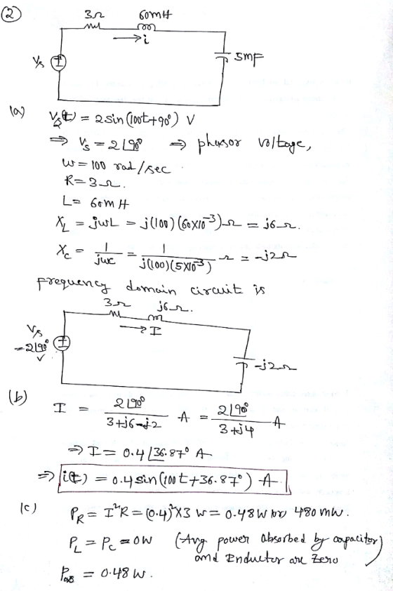
 Name: Section: Jan. 31, 2018 1. Consider the circuit shown in figure 1 (a) Write the mesh-current equations for the circuit. DO NOT SOLVE. (b) Write the node.voltage equations for the cireuit. DO NOT SOLVE 2. Consider the circuit shown in figure 2. The sinusoidal source is v,(04 sin (100t+90) volts (a) Transform the circuit to the frequency domain. (b) Use phasors with the mesh-current method to find the steady state expression for i(t). (c) Find the average power absorbed...
Consider the circuit shown in (Figure 1). Suppose that v1=240V, v2=115V, and v3=470V. Part A. Use...
 Consider the circuit shown in (Figure 1). Suppose that
v1=240V, v2=115V, and v3=470V.
Part A. Use the mesh-current method to find the magnitude of
the total power developed in the circuit.
Part B. Find the magnitude of the total power dissipated in
the circuit.
6Ω ΙΩ 3Ω 2Ω 4Ω 5Ω
Consider the circuit shown in (Figure 1). Suppose that
v1=240V, v2=115V, and v3=470V.
Part A. Use the mesh-current method to find the magnitude of
the total power developed in the circuit.
Part B. Find the magnitude of the total power dissipated in
the circuit.
6Ω ΙΩ 3Ω 2Ω 4Ω 5Ω
Problem #1: Circuit Analysis and Thevenin Equivalent [20 points] The bridge circuit is connected to a...
 Problem #1: Circuit Analysis and Thevenin Equivalent [20 points] The bridge circuit is connected to a load RL between terminals (a, b) as shown (a) Use node-voltage method to solve for VTH respect to terminal (a, b) (b) Use mesh-current method to solve for isc respect to terminal (a, b) 5Ω 2Ω 2 Ri b al 16 V 4Ω 2Ω
Consider the circuit shown in (Figure 1). Suppose that is = 5.2 A . Use the...
 Consider the circuit shown in (Figure 1). Suppose
that is = 5.2 A .
Use the mesh-current method to find the magnitude of the power
delivered by the 5.2 A current source.
Find the magnitude of the total power delivered to the
circuit.
Find the magnitude of the total power dissipated in the
circuit.
38 Ω 6Ω 5 V 30 Ω 67 V 12Ω 40 Ω
Consider the circuit shown in (Figure 1). Suppose
that is = 5.2 A .
Use the mesh-current method to find the magnitude of the power
delivered by the 5.2 A current source.
Find the magnitude of the total power delivered to the
circuit.
Find the magnitude of the total power dissipated in the
circuit.
38 Ω 6Ω 5 V 30 Ω 67 V 12Ω 40 Ω
4. Use the mesh-current method to find i, iandi in the circuit shown in Figure 4....
 4. Use the mesh-current method to find i, iandi in the circuit shown in Figure 4. W 1.50 Fig. 4 5. Use the mesh-current method to find i, toi, in the circuit shown in Figure 5. 250 m . 1000 200 V +) 500 10 Fig. 5 6. Use the mesh-current method to find the power that the current source delivers to the circuit shown in Figure 6. 5.60 0.80 30 A Fig. 6
Please box all answers for a thumbs up Consider the circuit shown in (Figure 1). Suppose...
 Please box all answers for a thumbs up
Consider the circuit shown in (Figure 1). Suppose that R = 7 kN. Figure K 1 of 1 Σ 40 ΚΩ 4 kΩ 2.5 kΩ 120 v 360 ΚΩ ()s.4 mA 390 kΩ 1.3 R 2 kΩ Part A Find the current i, in the circuit by making a succession of appropriate source transformations. Express your answer to three significant figures and include the appropriate units. μΑ ? io = Value mA...
Please box all answers for a thumbs up
Consider the circuit shown in (Figure 1). Suppose that R = 7 kN. Figure K 1 of 1 Σ 40 ΚΩ 4 kΩ 2.5 kΩ 120 v 360 ΚΩ ()s.4 mA 390 kΩ 1.3 R 2 kΩ Part A Find the current i, in the circuit by making a succession of appropriate source transformations. Express your answer to three significant figures and include the appropriate units. μΑ ? io = Value mA...
For the circuit shown, find the steady-state voltage across the inductor v (t), when us 1 (t) = 2...
 For the circuit shown, find the steady-state voltage across the inductor v (t), when us 1 (t) = 20 cos(1000t) V, vs2(t) = 30 cos(1000t-90') V, using: (a) The mesh-current method (b) The node-voltage method. (c) The Source transformation Method (d) The superposition Principle (e The Thevenin's equivalent at the terminals a-b. 200μF VL 15mH Vs2 10Ω
For the circuit shown, find the steady-state voltage across the inductor v (t), when us 1 (t) = 20 cos(1000t) V, vs2(t) =...
For the circuit shown, find the steady-state voltage across the inductor v (t), when us 1 (t) = 20 cos(1000t) V, vs2(t) = 30 cos(1000t-90') V, using: (a) The mesh-current method (b) The node-voltage method. (c) The Source transformation Method (d) The superposition Principle (e The Thevenin's equivalent at the terminals a-b. 200μF VL 15mH Vs2 10Ω
For the circuit shown, find the steady-state voltage across the inductor v (t), when us 1 (t) = 20 cos(1000t) V, vs2(t) =...
2. Consider the circuit shown in figure 2. The sinusoidal source is v()(5) sin (500t+90°) volts, R= 3Ω, L=12mH, and C=1000 μF. (a) Transform the circuit to the frequency domain. (b) Use phasors...
 2. Consider the circuit shown in figure 2. The sinusoidal source is v()(5) sin (500t+90°) volts, R= 3Ω, L=12mH, and C=1000 μF. (a) Transform the circuit to the frequency domain. (b) Use phasors with the loop analysis to find the steady state expression for i(). (c) Find the average power absorbed by each passive circuit element (PR. P Pc), and also Pva We were unable to transcribe this image
2. Consider the circuit shown in figure 2. The sinusoidal source...
2. Consider the circuit shown in figure 2. The sinusoidal source is v()(5) sin (500t+90°) volts, R= 3Ω, L=12mH, and C=1000 μF. (a) Transform the circuit to the frequency domain. (b) Use phasors with the loop analysis to find the steady state expression for i(). (c) Find the average power absorbed by each passive circuit element (PR. P Pc), and also Pva We were unable to transcribe this image
2. Consider the circuit shown in figure 2. The sinusoidal source...
Please answer showing detailed work. PartA Consider the circuit shown in (Figure 1). Suppose that k...
 Please answer showing detailed work.
PartA Consider the circuit shown in (Figure 1). Suppose that k 135 and V 180 V Use the mesh-current method to calculate the power delivered by the dependent voltage source Express your answer to three significant figures and include the appropriate units Figure 1 of 1 .1 Value Units Paelratue Submit 10Ω 30Ω ki, Provide Feedback 20Ω
Please answer showing detailed work.
PartA Consider the circuit shown in (Figure 1). Suppose that k 135 and V 180 V Use the mesh-current method to calculate the power delivered by the dependent voltage source Express your answer to three significant figures and include the appropriate units Figure 1 of 1 .1 Value Units Paelratue Submit 10Ω 30Ω ki, Provide Feedback 20Ω
 Name: Section: Jan. 31, 2018 1. Consider the circuit shown in figure 1 (a) Write the mesh-current equations for the circuit. DO NOT SOLVE. (b) Write the node.voltage equations for the cireuit. DO NOT SOLVE 2. Consider the circuit shown in figure 2. The sinusoidal source is v,(04 sin (100t+90) volts (a) Transform the circuit to the frequency domain. (b) Use phasors with the mesh-current method to find the steady state expression for i(t). (c) Find the average power absorbed...
 Consider the circuit shown in (Figure 1). Suppose that
v1=240V, v2=115V, and v3=470V.
Part A. Use the mesh-current method to find the magnitude of
the total power developed in the circuit.
Part B. Find the magnitude of the total power dissipated in
the circuit.
6Ω ΙΩ 3Ω 2Ω 4Ω 5Ω
Consider the circuit shown in (Figure 1). Suppose that
v1=240V, v2=115V, and v3=470V.
Part A. Use the mesh-current method to find the magnitude of
the total power developed in the circuit.
Part B. Find the magnitude of the total power dissipated in
the circuit.
6Ω ΙΩ 3Ω 2Ω 4Ω 5Ω
 Problem #1: Circuit Analysis and Thevenin Equivalent [20 points] The bridge circuit is connected to a load RL between terminals (a, b) as shown (a) Use node-voltage method to solve for VTH respect to terminal (a, b) (b) Use mesh-current method to solve for isc respect to terminal (a, b) 5Ω 2Ω 2 Ri b al 16 V 4Ω 2Ω
 Consider the circuit shown in (Figure 1). Suppose
that is = 5.2 A .
Use the mesh-current method to find the magnitude of the power
delivered by the 5.2 A current source.
Find the magnitude of the total power delivered to the
circuit.
Find the magnitude of the total power dissipated in the
circuit.
38 Ω 6Ω 5 V 30 Ω 67 V 12Ω 40 Ω
Consider the circuit shown in (Figure 1). Suppose
that is = 5.2 A .
Use the mesh-current method to find the magnitude of the power
delivered by the 5.2 A current source.
Find the magnitude of the total power delivered to the
circuit.
Find the magnitude of the total power dissipated in the
circuit.
38 Ω 6Ω 5 V 30 Ω 67 V 12Ω 40 Ω
 4. Use the mesh-current method to find i, iandi in the circuit shown in Figure 4. W 1.50 Fig. 4 5. Use the mesh-current method to find i, toi, in the circuit shown in Figure 5. 250 m . 1000 200 V +) 500 10 Fig. 5 6. Use the mesh-current method to find the power that the current source delivers to the circuit shown in Figure 6. 5.60 0.80 30 A Fig. 6
 Please box all answers for a thumbs up
Consider the circuit shown in (Figure 1). Suppose that R = 7 kN. Figure K 1 of 1 Σ 40 ΚΩ 4 kΩ 2.5 kΩ 120 v 360 ΚΩ ()s.4 mA 390 kΩ 1.3 R 2 kΩ Part A Find the current i, in the circuit by making a succession of appropriate source transformations. Express your answer to three significant figures and include the appropriate units. μΑ ? io = Value mA...
Please box all answers for a thumbs up
Consider the circuit shown in (Figure 1). Suppose that R = 7 kN. Figure K 1 of 1 Σ 40 ΚΩ 4 kΩ 2.5 kΩ 120 v 360 ΚΩ ()s.4 mA 390 kΩ 1.3 R 2 kΩ Part A Find the current i, in the circuit by making a succession of appropriate source transformations. Express your answer to three significant figures and include the appropriate units. μΑ ? io = Value mA...
 For the circuit shown, find the steady-state voltage across the inductor v (t), when us 1 (t) = 20 cos(1000t) V, vs2(t) = 30 cos(1000t-90') V, using: (a) The mesh-current method (b) The node-voltage method. (c) The Source transformation Method (d) The superposition Principle (e The Thevenin's equivalent at the terminals a-b. 200μF VL 15mH Vs2 10Ω
For the circuit shown, find the steady-state voltage across the inductor v (t), when us 1 (t) = 20 cos(1000t) V, vs2(t) =...
For the circuit shown, find the steady-state voltage across the inductor v (t), when us 1 (t) = 20 cos(1000t) V, vs2(t) = 30 cos(1000t-90') V, using: (a) The mesh-current method (b) The node-voltage method. (c) The Source transformation Method (d) The superposition Principle (e The Thevenin's equivalent at the terminals a-b. 200μF VL 15mH Vs2 10Ω
For the circuit shown, find the steady-state voltage across the inductor v (t), when us 1 (t) = 20 cos(1000t) V, vs2(t) =...
 2. Consider the circuit shown in figure 2. The sinusoidal source is v()(5) sin (500t+90°) volts, R= 3Ω, L=12mH, and C=1000 μF. (a) Transform the circuit to the frequency domain. (b) Use phasors with the loop analysis to find the steady state expression for i(). (c) Find the average power absorbed by each passive circuit element (PR. P Pc), and also Pva We were unable to transcribe this image
2. Consider the circuit shown in figure 2. The sinusoidal source...
2. Consider the circuit shown in figure 2. The sinusoidal source is v()(5) sin (500t+90°) volts, R= 3Ω, L=12mH, and C=1000 μF. (a) Transform the circuit to the frequency domain. (b) Use phasors with the loop analysis to find the steady state expression for i(). (c) Find the average power absorbed by each passive circuit element (PR. P Pc), and also Pva We were unable to transcribe this image
2. Consider the circuit shown in figure 2. The sinusoidal source...
 Please answer showing detailed work.
PartA Consider the circuit shown in (Figure 1). Suppose that k 135 and V 180 V Use the mesh-current method to calculate the power delivered by the dependent voltage source Express your answer to three significant figures and include the appropriate units Figure 1 of 1 .1 Value Units Paelratue Submit 10Ω 30Ω ki, Provide Feedback 20Ω
Please answer showing detailed work.
PartA Consider the circuit shown in (Figure 1). Suppose that k 135 and V 180 V Use the mesh-current method to calculate the power delivered by the dependent voltage source Express your answer to three significant figures and include the appropriate units Figure 1 of 1 .1 Value Units Paelratue Submit 10Ω 30Ω ki, Provide Feedback 20Ω
Most questions answered within 3 hours.
-
An object in front of a concave mirror has a real image that is
11.5 cm...
asked 3 minutes ago -
Consider the reaction, C3 H8 + O2 --> CO2 + H2O. How many
moles of O2...
asked 1 hour ago -
You and your opponent both roll a fair die. If you both roll the
same number,...
asked 2 hours ago -
In a study of the accuracy of fast food drive-through orders,
Restaurant A had 257 accurate...
asked 2 hours ago -
Identify and describe in detail the four categories of
institutions that could be included in a...
asked 2 hours ago -
In python
class Customer:
def __init__(self, customer_id, last_name, first_name, phone_number, address):
self._customer_id = int(customer_id)
self._last_name =...
asked 2 hours ago -
What is an example of a limitation in implementing a new
ERP system and how it...
asked 2 hours ago -
In a section of 9.7cm of an artery with a radius of 2.6mm there
is a...
asked 2 hours ago -
the two carboxylic acid groups of aspartic acid have different
acidities with pKa values of 2.1...
asked 2 hours ago -
Would CuCO3 aqueous salt combined with calcium chloride
form a solid precipitate? If so, what would...
asked 2 hours ago -
How do ECM Solutions assist in embedding a culture of continuous
improvement in an organization? (Project...
asked 2 hours ago -
Directions
These directions introduce the idea of Essential Questions.
Since this may be a new concept...
asked 2 hours ago