
Homework Answers
Add Answer to:
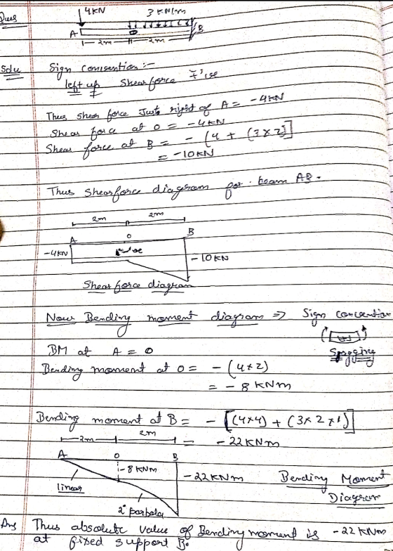
2.(49 points) The cantilever beam below is fixed at point B.Draw the shear and bending moment...
Use the graphical method to construct the shear-force and bending-moment diagrams for the beam shown.
 Use the graphical method to construct the shear-force and bending-moment diagrams for the beam shown. Label all significant points on each diagram and identify the maximum moments along with their respective locations. For all answers entered, use the sign convention for shear forces and bending moments. (a) Find the location x and the corresponding bending moment M at the one point between A and B at which the shear force equals zero. (b) Consider the entire beam and determine the maximum positive...
Use the graphical method to construct the shear-force and bending-moment diagrams for the beam shown. Label...
 Use the graphical method to construct the shear-force and bending-moment diagrams for the beam shown. Label all significant points on each diagram and identify the maximum moments along with their respective locations. For all answers entered, use the sign convention for shear forces and bending moments (a) Find the location x and the corresponding bending moment M at the one point between A and D at which the shear force equals zero. (b) Consider the entire beam and determine the...
(35 points) (a) Draw the shear and bending moment diagrams for the cantilever beam shown. (b)...
 (35 points) (a) Draw the shear and bending moment diagrams for the cantilever beam shown. (b) Specify the maximum positive and negative shear force and bending moment. Take L1 300 mm, L2 -300 mm, q 100 N/m. 2.
For the beam shown, draw the shear and bending moment diagrams and determine the magnitude and...
 For the beam shown, draw the shear and bending moment diagrams and determine the magnitude and location of the maximum absolute values of bending moment knowing that a) M 0, b) M 12 kNm.(7, 30) 20 kN/m С В М A 2m- 2 m
Draw neat and well-labelled shear and bending moment diagrams for the compound beam shown below B...
 Draw neat and well-labelled shear and bending moment diagrams for the compound beam shown below Beam ABC consists of two segments connected by a hinge at B. There is a fixed support at A and a roller support m C. The sapport reactions have already been calculated for you. Degree of each polynomial. Location of the points with zero shear and values of peak moments. Report the magnitwdes of maximum sheaer and bending moenent in the boves below (absolute value:...
Draw the shear and bending-moment diagrams for the beam and loading shown.
 Required information Consider the given beam and loading. Draw the shear and bending-moment diagrams for the beam and loading shown.Determine the maximum absolute values of the shear and bending moment. (Round the final answer to one decimal place.) The maximum absolute shear force is _______ KN. The maximum absolute bending moment is _______ kN.m.
For the beam and loading shown, draw the shear and bending moment diagrams, and determine the...
 For the beam and loading shown, draw the shear and bending moment diagrams, and determine the magnitude and location of the maximum shear and bending moment. 2 kN/m AC D 6 NT 3kN/m lm-- 1.2 m 0.6 m
4. For the beam and loading shown, draw the shear force and bending moment diagrams and...
 4. For the beam and loading shown, draw the shear force and bending moment diagrams and determine the maximum bending and shear force and their locations. 20 KN 40 KN B D 250 mm |--2.5 m- 3m-4-2 m 80 mm 5. For the beam and loading shown, draw the shear force and bending moment diagrams and determine the maximum bending and shear force and their locations. 50 KN
(a) Draw the load (FBD), shear, and bending moment diagrams for the beam shown. (b) Write...
 (a) Draw the load (FBD), shear, and bending moment diagrams for the beam shown. (b) Write the equations for Vix) and M(x), taking the origin at the left end of the beam. (c) Taking the cross section to be C 380 x 74 (page 812 of Text), determine the maximum bending stress at the section where the moment (absolute value) is maximum. (d) Determine the maximum shear stress at the section 2 m from the left end. 40 kN/m15 kN...
For the beam and loading shown draw the shear and bending moment diagrams and then find...
 For the beam and loading shown draw the shear and bending moment
diagrams and then find the maximum absolute values of the shear and
bending moment.
1. For the beam and loading shown draw the shear and bending-moment diagrams and then find the maximum absolute values of the shear and bending moment. 300 N/m 4 m
For the beam and loading shown draw the shear and bending moment
diagrams and then find the maximum absolute values of the shear and
bending moment.
1. For the beam and loading shown draw the shear and bending-moment diagrams and then find the maximum absolute values of the shear and bending moment. 300 N/m 4 m
 Use the graphical method to construct the shear-force and bending-moment diagrams for the beam shown. Label all significant points on each diagram and identify the maximum moments along with their respective locations. For all answers entered, use the sign convention for shear forces and bending moments. (a) Find the location x and the corresponding bending moment M at the one point between A and B at which the shear force equals zero. (b) Consider the entire beam and determine the maximum positive...
 Use the graphical method to construct the shear-force and bending-moment diagrams for the beam shown. Label all significant points on each diagram and identify the maximum moments along with their respective locations. For all answers entered, use the sign convention for shear forces and bending moments (a) Find the location x and the corresponding bending moment M at the one point between A and D at which the shear force equals zero. (b) Consider the entire beam and determine the...
 (35 points) (a) Draw the shear and bending moment diagrams for the cantilever beam shown. (b) Specify the maximum positive and negative shear force and bending moment. Take L1 300 mm, L2 -300 mm, q 100 N/m. 2.
 For the beam shown, draw the shear and bending moment diagrams and determine the magnitude and location of the maximum absolute values of bending moment knowing that a) M 0, b) M 12 kNm.(7, 30) 20 kN/m С В М A 2m- 2 m
 Draw neat and well-labelled shear and bending moment diagrams for the compound beam shown below Beam ABC consists of two segments connected by a hinge at B. There is a fixed support at A and a roller support m C. The sapport reactions have already been calculated for you. Degree of each polynomial. Location of the points with zero shear and values of peak moments. Report the magnitwdes of maximum sheaer and bending moenent in the boves below (absolute value:...
 For the beam and loading shown, draw the shear and bending moment diagrams, and determine the magnitude and location of the maximum shear and bending moment. 2 kN/m AC D 6 NT 3kN/m lm-- 1.2 m 0.6 m
 4. For the beam and loading shown, draw the shear force and bending moment diagrams and determine the maximum bending and shear force and their locations. 20 KN 40 KN B D 250 mm |--2.5 m- 3m-4-2 m 80 mm 5. For the beam and loading shown, draw the shear force and bending moment diagrams and determine the maximum bending and shear force and their locations. 50 KN
 (a) Draw the load (FBD), shear, and bending moment diagrams for the beam shown. (b) Write the equations for Vix) and M(x), taking the origin at the left end of the beam. (c) Taking the cross section to be C 380 x 74 (page 812 of Text), determine the maximum bending stress at the section where the moment (absolute value) is maximum. (d) Determine the maximum shear stress at the section 2 m from the left end. 40 kN/m15 kN...
 For the beam and loading shown draw the shear and bending moment
diagrams and then find the maximum absolute values of the shear and
bending moment.
1. For the beam and loading shown draw the shear and bending-moment diagrams and then find the maximum absolute values of the shear and bending moment. 300 N/m 4 m
For the beam and loading shown draw the shear and bending moment
diagrams and then find the maximum absolute values of the shear and
bending moment.
1. For the beam and loading shown draw the shear and bending-moment diagrams and then find the maximum absolute values of the shear and bending moment. 300 N/m 4 m
Most questions answered within 3 hours.
-
Derive ground state term symbols. Use notation 2S(1/2) for state
2S1/2
a) d5
b) f3
c)...
asked 15 minutes ago -
A sample of size 31 will be drawn from a population with mean 39
and standard...
asked 54 minutes ago -
What is the effect on the P-value when a test is changed from a
two-tailed hypothesis...
asked 59 minutes ago -
I wish to estimate µ, the mean of a population. After I collect
and an-
alyze...
asked 1 hour ago -
At a local university, you poll a group of 115 students and find
that 37 of...
asked 1 hour ago -
Gladstone company tracks the number of units purchased and sold
throughout each accounting period but applies...
asked 1 hour ago -
When determining if a molecule's configuration is E or Z, what
determines the higher priority groups?
asked 1 hour ago -
13. What is the amount
of conversion cost transferred to finished goods? (Round
your intermediate calculations...
asked 1 hour ago -
Sulfuric Acid is a "strong" acid, but only releases a single
proton when it dissolves. What...
asked 1 hour ago -
The
second floor of a house is 6 m above the street level. How much
work...
asked 1 hour ago -
What uncontrollable factor(s) contributed to Hong Kong Disney’s
poor performance during its first year?
asked 1 hour ago -
You are interested in whether students that have a male
instructors perform differently on exams. To...
asked 1 hour ago