
Homework Answers
Question a:
the loop transfer function is given by L(z) = 0.5*0.24*z*(z+0.5)/((z-1)*(z-0.4)^2)
L(z) = (0.12 z^2 + 0.06 z) / (z^3 - 1.8 z^2 + 0.96 z - 0.16)
The closed loop transfer function is given by
T(z) = L(z) / (1+L(z)) = (0.12 z^2 + 0.06 z) / (z^3 - 1.8 z^2 + 0.96 z - 0.16 + 0.12 z^2 + 0.06 z))
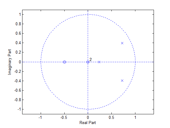
T(z) = (0.12 z^2 + 0.06 z) / (z^3 - 1.68 z^2 + 1.02 z - 0.16)
The poles of the closed loop transfer function are given by: z^3 - 1.68 z^2 + 1.02 z - 0.16 = 0
The poles are given below.
0.7224 + 0.3979i
0.7224 - 0.3979i
0.2353
MATLAB is used to plot the pole zero diagram.
code to plot:
figure;zplane([0.12 0.06],[1 -1.68 1.02 -0.16]);
With T = 0.5, and zero order hold method to convert from discrete to continuous domains, we have,
Tc(s) {continuous counterpart of discrete domain transfer function T(z)} will be equal to
Tc(s) =
0.07413 s^2 + 0.8756 s + 3.364
---------------------------------
s^3 + 3.665 s^2 + 3.394 s + 3.364
The poles and zeros are given by
Poles:
-2.8942
-0.3855 + 1.0069i
-0.3855 - 1.0069i
Zeros:
-5.9058 + 3.2412i
-5.9058 - 3.2412i
The polez-zero diagram is plotted below.

Question (c):
The dominant poles are the closest poles to the jw axis in s plane. Basically these are are poles that dictate the most of the response of the system in most cases. This is because, the poles which are closer to jw axis have higher time constant {time constant and location of pole are inversely related: closer the pole to jw axis larger its tie constant.} which have larger amount of time to settle and therefore the response of the overall system with dominant pole pair and a bunch of non-dominant poles will largely look like the {close match} response of the dominant pole pair it self.
In the above case, we have poles located at -2.8942, -0.3855 + 1.0069i, -0.3855 - 1.0069i. The real part of the complex poles {this is their distance from jw axis, a factor that indicates how close they are} is -0.3855 which is 7.5 times as close as the other pole to jw axis { usually this greater than 5 times considered}.Therefore, 0.3855 + 1.0069i, -0.3855 - 1.0069i are the dominant pole pairs and -2.8942 is non dominant pole.
Add Answer to:
Question 3 The block diagram of a digital control system is given in Fig. 2. R(Z)...
a) List the relative attributes of using digital processing techniques compared to traditional analogue hardware for signal processing. [5 marks] b) Sketch a z-plane diagram including the unit ci...
 a) List the relative attributes of using digital processing techniques compared to traditional analogue hardware for signal processing. [5 marks] b) Sketch a z-plane diagram including the unit circle. You have four Poles and two Zeros that you can place on the z-plane diagram. Place them in a position which would provide a digital band-stop filter characteristic with the 'notch' at a n/2 Justify your placement of the poles and zeros. 5 marks] c) The z-plane pole-zero plots of two...
Answer the following questions for a causal digital filter with the following system function H(z) 23-2+0.64z-0.64 1-1. (0.5 point) Locate the poles and zeros of H(z) on the z-plane. (sol) 1-2. (...
 Answer the following questions for a causal digital filter with the following system function H(z) 23-2+0.64z-0.64 1-1. (0.5 point) Locate the poles and zeros of H(z) on the z-plane. (sol) 1-2. (1.5 point) Sketch the magnitude spectrum, H(e i), of the filter. Find the exact values of lH(eml. IH(efr/2)I, and IH(e") , (sol) 1-3. (1 point) Relocate only one pole so that 9 s Hle)s 10 (sol) 1-4 (1 point) Take the inverse Z-transform on H(z) to find the impulse...
Q. 1 (5 marks) For the system in Fig. (a). Assume proportion control, Gc(s)-K, sketch the root lo...
 pls answer dont just copy other solution or ur catching a
dislike
Q. 1 (5 marks) For the system in Fig. (a). Assume proportion control, Gc(s)-K, sketch the root locus for the closed-loop system (b). Using the angle condition, prove that s12 +j2 is not on the root locus. (c). Design a lead compensator Ge(s) - K such that the dominant closed-loop poles are located at s1--2 2. (d), What are the zero and pole of lead compensator G() (e)....
pls answer dont just copy other solution or ur catching a
dislike
Q. 1 (5 marks) For the system in Fig. (a). Assume proportion control, Gc(s)-K, sketch the root locus for the closed-loop system (b). Using the angle condition, prove that s12 +j2 is not on the root locus. (c). Design a lead compensator Ge(s) - K such that the dominant closed-loop poles are located at s1--2 2. (d), What are the zero and pole of lead compensator G() (e)....
Q. 1 (10 marks) For the system in Fig. 1 (a) Assume proportion control. Ge(s) =...
 Q. 1 (10 marks) For the system in Fig. 1 (a) Assume proportion control. Ge(s) = K. sketch the root locus for the closed-loop system (b). Using the angle condition, prove that s1 =-2 +j2 is not on the root locus. (c). Design a lead compensator such that the dominant closed-loop poles are located at s-2tj2. (d). What are the zero and pole of lead compensator Ge(s)? (e). With Ge (s) has the zero and pole found in (c), sketch...
3 .0.2) 0(z) ℉.20-1011,. +20s+101)(s+20) 20), the damping ratio for the dominant Problem 2: For a...
 3 .0.2) 0(z) ℉.20-1011,. +20s+101)(s+20) 20), the damping ratio for the dominant Problem 2: For a unity feedback system with closed loop poles is to be 0.4, and the settling time is to be 0.5 second for the compensated system. a. b. c. d. Find the coordinates of the dominant poles. Find the location of the compensator zero if the compensator pole is at -15 (lead compensator) Find the required system gain. Compare the performance of the uncompensated and compensated...
Q2. Fig Q2 shows the block diagram of an unstable system with transfer function G(s) -...
 Q2. Fig Q2 shows the block diagram of an unstable system with transfer function G(s) - under the control of a lead compensator (a) Using the Routh's stability criterion, determine the conditions on k and a so that the closed-loop system is stable, and sketch the region on the (k, a)- plane where the conditions are satisfied. Hence, determine the minimum value of k for the lead compensator to be a feasible stabilizing controller. (10 marks) (b) Suppose α-2. Given...
C(s) G(s) Figure 1: A block diagram for Problems 1-4 For the given unity feedback system with G(s...
 C(s) G(s) Figure 1: A block diagram for Problems 1-4 For the given unity feedback system with G(s) - s 5)3' (a) Find the location of the dominant poles to yield a 1.2 second settling time and overshoot of 15% (b) If a compensator with a zero at-1 is used to achieve the conditions of Part a, what must be the angular contribution of the compensator pole be? (c) Find the location of the compensator pole. (d) Find the gain...
Please answer ALL parts to this digital signal processing question: Please show your working The figure below repr...
 Please answer ALL parts to this digital signal processing question:
Please show your working
The figure below represents a biquadratic digital filter in state-variable realisation form: Unit delay delay win-2 The values of the multipliers are as follows Answer the following questions, giving answers to four decimal places. PART 1 Determine the time domain equations that relate the input r[n] to the intermediate system variable ton and the output yin] to the intermediate system variable and complete the following: PART...
Please answer ALL parts to this digital signal processing question:
Please show your working
The figure below represents a biquadratic digital filter in state-variable realisation form: Unit delay delay win-2 The values of the multipliers are as follows Answer the following questions, giving answers to four decimal places. PART 1 Determine the time domain equations that relate the input r[n] to the intermediate system variable ton and the output yin] to the intermediate system variable and complete the following: PART...
Question 2 (14 Marks) Consider Fig. Q2 below. zi Z 23 R12002 R 1202 R 602...
 Question 2 (14 Marks) Consider Fig. Q2 below. zi Z 23 R12002 R 1202 R 602 Xc 600 X.32492 Fig. Q2 The voltage Vrms = 240020° V is applied to a load Zi, Zz and Zs. a) Determine real, reactive and complex power by each load. (COI: PO1: C4 - 9 Marks) b) Determine total complex power in polar form, (C01: P01: C3-1 Marks) c) Sketch all the complex power S., S2. Ss and Stalin vector representation in plane diagram....
3-21. The block diagram of a control system is shown in Fig. 3P-21. (a) Draw an...
 3-21. The block diagram of a control system is shown in Fig. 3P-21. (a) Draw an equivalent SFG for the system. (b) Find the following transfer functions by applying the gain formula of the SFG directly to the block diagram. Y(s) Y(s) E(s) E(s) R(s)[N=0 N(s)R=0 R(s) N= N(s) R-0 (c) Compare the answers by applying the gain formula to the equivalent SFG. N() G (s) E(s) YS G () G3(s) H () Figure 3P-21
 a) List the relative attributes of using digital processing techniques compared to traditional analogue hardware for signal processing. [5 marks] b) Sketch a z-plane diagram including the unit circle. You have four Poles and two Zeros that you can place on the z-plane diagram. Place them in a position which would provide a digital band-stop filter characteristic with the 'notch' at a n/2 Justify your placement of the poles and zeros. 5 marks] c) The z-plane pole-zero plots of two...
 Answer the following questions for a causal digital filter with the following system function H(z) 23-2+0.64z-0.64 1-1. (0.5 point) Locate the poles and zeros of H(z) on the z-plane. (sol) 1-2. (1.5 point) Sketch the magnitude spectrum, H(e i), of the filter. Find the exact values of lH(eml. IH(efr/2)I, and IH(e") , (sol) 1-3. (1 point) Relocate only one pole so that 9 s Hle)s 10 (sol) 1-4 (1 point) Take the inverse Z-transform on H(z) to find the impulse...
 pls answer dont just copy other solution or ur catching a
dislike
Q. 1 (5 marks) For the system in Fig. (a). Assume proportion control, Gc(s)-K, sketch the root locus for the closed-loop system (b). Using the angle condition, prove that s12 +j2 is not on the root locus. (c). Design a lead compensator Ge(s) - K such that the dominant closed-loop poles are located at s1--2 2. (d), What are the zero and pole of lead compensator G() (e)....
pls answer dont just copy other solution or ur catching a
dislike
Q. 1 (5 marks) For the system in Fig. (a). Assume proportion control, Gc(s)-K, sketch the root locus for the closed-loop system (b). Using the angle condition, prove that s12 +j2 is not on the root locus. (c). Design a lead compensator Ge(s) - K such that the dominant closed-loop poles are located at s1--2 2. (d), What are the zero and pole of lead compensator G() (e)....
 Q. 1 (10 marks) For the system in Fig. 1 (a) Assume proportion control. Ge(s) = K. sketch the root locus for the closed-loop system (b). Using the angle condition, prove that s1 =-2 +j2 is not on the root locus. (c). Design a lead compensator such that the dominant closed-loop poles are located at s-2tj2. (d). What are the zero and pole of lead compensator Ge(s)? (e). With Ge (s) has the zero and pole found in (c), sketch...
 3 .0.2) 0(z) ℉.20-1011,. +20s+101)(s+20) 20), the damping ratio for the dominant Problem 2: For a unity feedback system with closed loop poles is to be 0.4, and the settling time is to be 0.5 second for the compensated system. a. b. c. d. Find the coordinates of the dominant poles. Find the location of the compensator zero if the compensator pole is at -15 (lead compensator) Find the required system gain. Compare the performance of the uncompensated and compensated...
 Q2. Fig Q2 shows the block diagram of an unstable system with transfer function G(s) - under the control of a lead compensator (a) Using the Routh's stability criterion, determine the conditions on k and a so that the closed-loop system is stable, and sketch the region on the (k, a)- plane where the conditions are satisfied. Hence, determine the minimum value of k for the lead compensator to be a feasible stabilizing controller. (10 marks) (b) Suppose α-2. Given...
 C(s) G(s) Figure 1: A block diagram for Problems 1-4 For the given unity feedback system with G(s) - s 5)3' (a) Find the location of the dominant poles to yield a 1.2 second settling time and overshoot of 15% (b) If a compensator with a zero at-1 is used to achieve the conditions of Part a, what must be the angular contribution of the compensator pole be? (c) Find the location of the compensator pole. (d) Find the gain...
 Please answer ALL parts to this digital signal processing question:
Please show your working
The figure below represents a biquadratic digital filter in state-variable realisation form: Unit delay delay win-2 The values of the multipliers are as follows Answer the following questions, giving answers to four decimal places. PART 1 Determine the time domain equations that relate the input r[n] to the intermediate system variable ton and the output yin] to the intermediate system variable and complete the following: PART...
Please answer ALL parts to this digital signal processing question:
Please show your working
The figure below represents a biquadratic digital filter in state-variable realisation form: Unit delay delay win-2 The values of the multipliers are as follows Answer the following questions, giving answers to four decimal places. PART 1 Determine the time domain equations that relate the input r[n] to the intermediate system variable ton and the output yin] to the intermediate system variable and complete the following: PART...
 Question 2 (14 Marks) Consider Fig. Q2 below. zi Z 23 R12002 R 1202 R 602 Xc 600 X.32492 Fig. Q2 The voltage Vrms = 240020° V is applied to a load Zi, Zz and Zs. a) Determine real, reactive and complex power by each load. (COI: PO1: C4 - 9 Marks) b) Determine total complex power in polar form, (C01: P01: C3-1 Marks) c) Sketch all the complex power S., S2. Ss and Stalin vector representation in plane diagram....
 3-21. The block diagram of a control system is shown in Fig. 3P-21. (a) Draw an equivalent SFG for the system. (b) Find the following transfer functions by applying the gain formula of the SFG directly to the block diagram. Y(s) Y(s) E(s) E(s) R(s)[N=0 N(s)R=0 R(s) N= N(s) R-0 (c) Compare the answers by applying the gain formula to the equivalent SFG. N() G (s) E(s) YS G () G3(s) H () Figure 3P-21
Most questions answered within 3 hours.
-
In Chapter 1 you created a program named Triangle in
which you displayed a seven-line triangle...
asked 10 minutes ago -
python
Define a function called print_values which takes a dictionary
object as a parameter. The function...
asked 15 minutes ago -
Research question: What are the differences between separately
stated and non separately stated transactions in an...
asked 33 minutes ago -
By using Arduino write a code that connects two LEDs to two
push-buttons. Each button controls...
asked 1 hour ago -
Bank of America has bonds that pay a coupon interest rate of 5.5
percent and mature...
asked 2 hours ago -
Problem: Patient Fees C++
You are to write a program that computes a patient’s bill for...
asked 3 hours ago -
In a population of interest, we know that, 77% drink coffee, and
23% drink tea. Assume...
asked 4 hours ago -
Given that f(x) = e-(x-1) for x > 1, determine the following
probabilities:
a) P(X <...
asked 4 hours ago -
A mechanic pushes a 2.60 ✕ 103-kg car from rest to a speed of v,
doing...
asked 4 hours ago -
International information systems result in all of the following
except:
A. improved quality of information flow....
asked 4 hours ago -
The president of the retailer Prime Products has just approached
the company’s bank with a request...
asked 4 hours ago -
If the carrying amount is $200,000 and recoverable amount is
$205000, the impairment amount is:
Select...
asked 4 hours ago