
Homework Answers


Add Answer to:
4. A T-shaped cross-sectional beam is loaded as shown in the figure. Determine the following a....
4. (30%) For a beam with a T-section as shown, the cross-sectional dimensions of 12 mm....
 4. (30%) For a beam with a T-section as shown, the cross-sectional dimensions of 12 mm. The centroid is 75 mm, h = 90 mm, t the beam are b 60 mm, h, at C and c 30 mm. At a certain section of the beam, the bending moment is M 5.4 kN m and the vertical shear force is V= 30 kN. (a) Show that the moment of inertia of the cross-section about the z axis (the neutral axis)...
Q4. (20 pts) A kN/m BEN. X mm The beam has the cross-sectional area and loaded...
 Q4. (20 pts) A kN/m BEN. X mm The beam has the cross-sectional area and loaded as shown. Draw the bending and shear force diagrams. Find the maximum bending stress in the beam. التسعي HO Z mm Y mm 3 m Z mm A=40 X=75 B=25 Y=125 Z=10
2. A cantilever beam is loaded as shown in the following figure. 1) Draw the shear...
 2. A cantilever beam is loaded as shown in the following figure. 1) Draw the shear force and bending moment diagrams 2) Calculate the maximum bending stress in the beam. S 3) Calculate themaximum transverse shear stress in the beam. 19 kN 3 kN/m NA 01 m 2 m 2 m 2 m
Draw the shear and moment diagrams for the loaded beam. After you have the diagrams, answer...
 Draw the shear and moment diagrams for the loaded beam. After you have the diagrams, answer the questions as a check on your work. 6 KN 5 kN/m 6 kN.m La mtu2m + 2m + 2m- 3 m 3m + +3m- 3m Questions: When x = 0.5 m, V = kNm When x = 3.2 m, V = kN.m When x = 6.0 m, V = kN.m When x = 8.2 m, V = kN.m The maximum (absolute value) shear...
For the following beam and loading shown in the figure; all the dimensions are measured in...
 For the following beam and loading shown in the figure; all the dimensions are measured in meter. Determine: a) Draw the free body diagram. b) Draw the shear and moment diagrams using an appropriate scale, (show all calculation details) c) The maximum normal stress due to bending. 15kN 240 mm 30 mm Im 50KN 10kN/m 1 16 mm 2 350 mm A B C D E 2m 2m 2m 3m 4m Beam cross-section
The beam has the loading and the shear diagram as shown. Consider a cross section between...
 The beam has the loading and the shear diagram as shown. Consider a cross section between C and D, determine: • the maximum shearing stress in that cross section, • the shearing stress at point Hon the web of the beam at the same cross section. 15 kN 8 KN 9 KN 12 KN -180 mm 40 mm А B C D E F H 3 m + 2m +2 m-42 m 4 m T 180 mm 12 KN 9...
A simply support beam is loaded as shown in the following figure. 1) Draw the shear...
 A simply support beam is loaded as shown in the following figure. 1) Draw the shear force and bending moment diagrams. 2) Calculate the maximum bending stress in the beam. 3) Calculate the maximum shear stress in the beam. G0 KN 30 kNm B0 kN/m H NA 0.1 m 3 m e 1.5m to 1.5m. 0.1 m
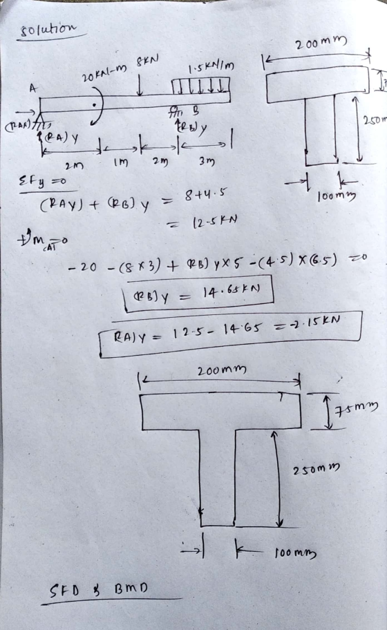
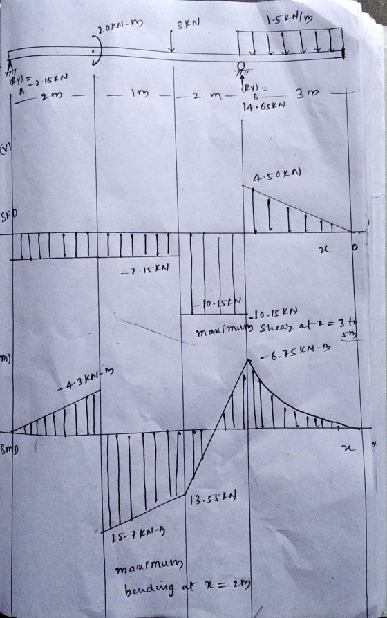
4. Figure 4 shows a beam with three supports at A, B and D. The beam...
 4. Figure 4 shows a beam with three supports at A, B and D. The
beam also has a pin connection at C. Draw the shear force diagram
and bending moment diagram of the beam. Calculate the maximum
bending stress and maximum shear stress of the beam.
200 mm 5 kN 3 kN/m 30 mm - 25 mm N IITIT 250 mm 3m — 3 m +1.5 m +1.5 m1 30 mm 100 mm Cross-section of beam Figure 4
4. Figure 4 shows a beam with three supports at A, B and D. The
beam also has a pin connection at C. Draw the shear force diagram
and bending moment diagram of the beam. Calculate the maximum
bending stress and maximum shear stress of the beam.
200 mm 5 kN 3 kN/m 30 mm - 25 mm N IITIT 250 mm 3m — 3 m +1.5 m +1.5 m1 30 mm 100 mm Cross-section of beam Figure 4
Draw the shear and moment diagrams for the loaded beam. After you have the diagrams, answer...
 Draw the shear and moment
diagrams for the loaded beam. After you have the diagrams, answer
the questions in order to gain confidence in your plots.
Draw the shear and moment diagrams for the loaded beam. After you have the diagrams, answer the questions in order to gain confidence in your plots. 2 kN 11 kN 5 kNm +3m +4m + 6m — +3m 8 KN Questions: When x = 2.1 m, V = KN.m When x = 5.7 m,...
Draw the shear and moment
diagrams for the loaded beam. After you have the diagrams, answer
the questions in order to gain confidence in your plots.
Draw the shear and moment diagrams for the loaded beam. After you have the diagrams, answer the questions in order to gain confidence in your plots. 2 kN 11 kN 5 kNm +3m +4m + 6m — +3m 8 KN Questions: When x = 2.1 m, V = KN.m When x = 5.7 m,...
For the beam shown below (neglect self-weight of the beam) 16 kN x 8 mm 19...
 For the beam shown below (neglect self-weight of the beam) 16 kN x 8 mm 19 kN 10 kN/m T 2 mm mm A4n - 3 m +3m → a. Draw the shear force and bending moment diagram. 2 mm Section X-X b. For the cross section x-x given, calculate the maximum tensile and compressive bending stress c. For the cross section X-X given, calculate the maximum shear stress
 4. (30%) For a beam with a T-section as shown, the cross-sectional dimensions of 12 mm. The centroid is 75 mm, h = 90 mm, t the beam are b 60 mm, h, at C and c 30 mm. At a certain section of the beam, the bending moment is M 5.4 kN m and the vertical shear force is V= 30 kN. (a) Show that the moment of inertia of the cross-section about the z axis (the neutral axis)...
 Q4. (20 pts) A kN/m BEN. X mm The beam has the cross-sectional area and loaded as shown. Draw the bending and shear force diagrams. Find the maximum bending stress in the beam. التسعي HO Z mm Y mm 3 m Z mm A=40 X=75 B=25 Y=125 Z=10
 2. A cantilever beam is loaded as shown in the following figure. 1) Draw the shear force and bending moment diagrams 2) Calculate the maximum bending stress in the beam. S 3) Calculate themaximum transverse shear stress in the beam. 19 kN 3 kN/m NA 01 m 2 m 2 m 2 m
 Draw the shear and moment diagrams for the loaded beam. After you have the diagrams, answer the questions as a check on your work. 6 KN 5 kN/m 6 kN.m La mtu2m + 2m + 2m- 3 m 3m + +3m- 3m Questions: When x = 0.5 m, V = kNm When x = 3.2 m, V = kN.m When x = 6.0 m, V = kN.m When x = 8.2 m, V = kN.m The maximum (absolute value) shear...
 For the following beam and loading shown in the figure; all the dimensions are measured in meter. Determine: a) Draw the free body diagram. b) Draw the shear and moment diagrams using an appropriate scale, (show all calculation details) c) The maximum normal stress due to bending. 15kN 240 mm 30 mm Im 50KN 10kN/m 1 16 mm 2 350 mm A B C D E 2m 2m 2m 3m 4m Beam cross-section
 The beam has the loading and the shear diagram as shown. Consider a cross section between C and D, determine: • the maximum shearing stress in that cross section, • the shearing stress at point Hon the web of the beam at the same cross section. 15 kN 8 KN 9 KN 12 KN -180 mm 40 mm А B C D E F H 3 m + 2m +2 m-42 m 4 m T 180 mm 12 KN 9...
 A simply support beam is loaded as shown in the following figure. 1) Draw the shear force and bending moment diagrams. 2) Calculate the maximum bending stress in the beam. 3) Calculate the maximum shear stress in the beam. G0 KN 30 kNm B0 kN/m H NA 0.1 m 3 m e 1.5m to 1.5m. 0.1 m
 4. Figure 4 shows a beam with three supports at A, B and D. The
beam also has a pin connection at C. Draw the shear force diagram
and bending moment diagram of the beam. Calculate the maximum
bending stress and maximum shear stress of the beam.
200 mm 5 kN 3 kN/m 30 mm - 25 mm N IITIT 250 mm 3m — 3 m +1.5 m +1.5 m1 30 mm 100 mm Cross-section of beam Figure 4
4. Figure 4 shows a beam with three supports at A, B and D. The
beam also has a pin connection at C. Draw the shear force diagram
and bending moment diagram of the beam. Calculate the maximum
bending stress and maximum shear stress of the beam.
200 mm 5 kN 3 kN/m 30 mm - 25 mm N IITIT 250 mm 3m — 3 m +1.5 m +1.5 m1 30 mm 100 mm Cross-section of beam Figure 4
 Draw the shear and moment
diagrams for the loaded beam. After you have the diagrams, answer
the questions in order to gain confidence in your plots.
Draw the shear and moment diagrams for the loaded beam. After you have the diagrams, answer the questions in order to gain confidence in your plots. 2 kN 11 kN 5 kNm +3m +4m + 6m — +3m 8 KN Questions: When x = 2.1 m, V = KN.m When x = 5.7 m,...
Draw the shear and moment
diagrams for the loaded beam. After you have the diagrams, answer
the questions in order to gain confidence in your plots.
Draw the shear and moment diagrams for the loaded beam. After you have the diagrams, answer the questions in order to gain confidence in your plots. 2 kN 11 kN 5 kNm +3m +4m + 6m — +3m 8 KN Questions: When x = 2.1 m, V = KN.m When x = 5.7 m,...
 For the beam shown below (neglect self-weight of the beam) 16 kN x 8 mm 19 kN 10 kN/m T 2 mm mm A4n - 3 m +3m → a. Draw the shear force and bending moment diagram. 2 mm Section X-X b. For the cross section x-x given, calculate the maximum tensile and compressive bending stress c. For the cross section X-X given, calculate the maximum shear stress
Most questions answered within 3 hours.
-
Water has significant IMF, which result in many of its unique
properties—high boiling point relative to...
asked 12 minutes ago -
I need help with an executive summary for Adidas Items to be
included are a discription...
asked 5 minutes ago -
19. Most progressive reform activists were white
and a. upper class. b. lower class. c. wokring...
asked 7 minutes ago -
If X is a binomial random variable with n = 8
and p = 0.2, the...
asked 17 minutes ago -
Seasonal or cyclical variation in a time-series model…
---exhibits irregular
variation that can be accounted for...
asked 18 minutes ago -
Please use Barney's VRIO framework of analysis to evaluate a
firm's competencies. Please choose a specific...
asked 31 minutes ago -
Where would you expect to have diabetes contributing to the most
DALYs in 2035, according to...
asked 32 minutes ago -
1.) Major league baseball salaries averaged $1.5 million with a
standard deviation of $1 million in...
asked 41 minutes ago -
A hedge fund is holding a three-year,
$10 million face value 6 percent annual coupon bond...
asked 53 minutes ago -
The focal length of a makeup (concave) mirror is 0.48 m. What
magnification does this mirror...
asked 57 minutes ago -
TRUE/FALSE
Long-lived assets that are tangible in nature, used in the
operations of the business, and...
asked 58 minutes ago -
A dragon biologist is setting up an experimental population of
1000 individuals. In dragons, pointy crests...
asked 1 hour ago