
Homework Answers

Add Answer to:
2. A cantilever beam is loaded as shown in the following figure. 1) Draw the shear...
A simply support beam is loaded as shown in the following figure. 1) Draw the shear...
 A simply support beam is loaded as shown in the following figure. 1) Draw the shear force and bending moment diagrams. 2) Calculate the maximum bending stress in the beam. 3) Calculate the maximum shear stress in the beam. G0 KN 30 kNm B0 kN/m H NA 0.1 m 3 m e 1.5m to 1.5m. 0.1 m
4. A T-shaped cross-sectional beam is loaded as shown in the figure. Determine the following a....
 4. A T-shaped cross-sectional beam is loaded as shown in the figure. Determine the following a. Sketch the internal shear force and bending moment diagrams for the beam. b. Calculate the maximum magnitude of the bending stress. Indicate where this occurs on the cross-section and along the length of the beam. c. Calculate the transverse shearing stress at the centroid of the cross-section using the maximum magnitude of the transverse shear force. - 200 mm 8 KN 1.5 kN/m 20...
The beam is loaded as shown in the diagram below. The beam is uniformly loaded at...
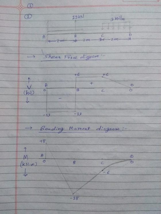
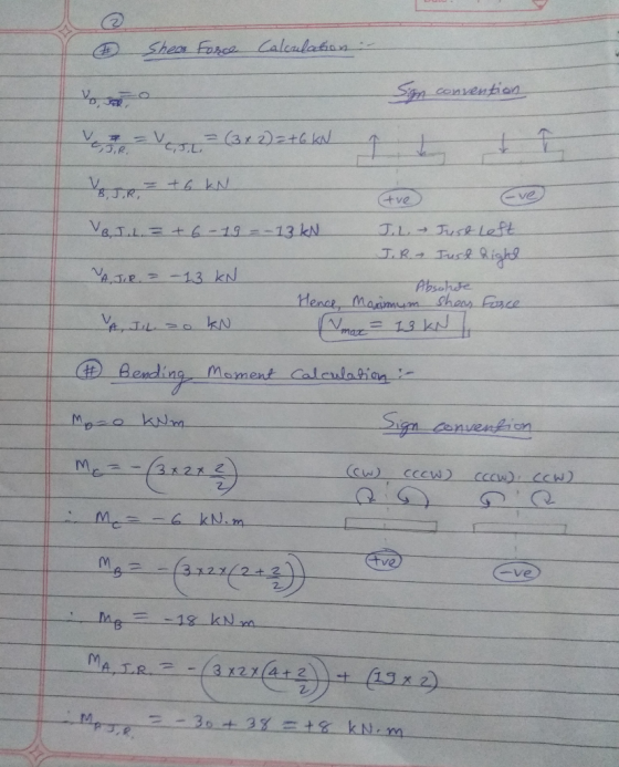
 The beam is loaded as shown in the diagram below. The beam is uniformly loaded at 3 kN/m for the length of 4 m from B. The beam also has two point loads, 4 KN at 2 m from A and 3 KN at 3 m from B. 2 KN 3 KN 3KN/m A 2 m 2 m 11 m 3 m Fig. Q2 Draw a shear force and bending moment diagram. Also determine the location of maximum bending moment...
4. A cantilever beam is loaded as shown in the figure. Using the method of sections...
 4. A cantilever beam is loaded as shown in the figure. Using the method of sections or the integration method, draw the shear force diagram and the bending moment diagram. If the beam cross-section is a 9 inch square, find the maximum bending stress 1200 lb 800 lb/ft 9" B 9" A Beam cross-section 8 ft 8 ft
Draw the shear force and bending moment diagrams for a cantilever beam as shown in Figure 3.
 Draw the shear force and bending moment diagrams for a cantilever beam as shown in Figure 3.
A cantilever beam with a 1-in-diameter round cross section is loaded at the tip with a...
 A cantilever beam with a 1-in-diameter round cross section is loaded at the tip with a transverse force of 1000 lbf, as shown in the figure. The cross section at the wall is also shown, with labeled points A at the top, B at the center, and C at the midpoint between A and B. Study the Cross section at the Problem 3-45 significance of the transverse shear stress in combination with bending by performing the following steps. (a) Assume...
(35 points) (a) Draw the shear and bending moment diagrams for the cantilever beam shown. (b)...
 (35 points) (a) Draw the shear and bending moment diagrams for the cantilever beam shown. (b) Specify the maximum positive and negative shear force and bending moment. Take L1 300 mm, L2 -300 mm, q 100 N/m. 2.
Q1. Draw the shear force and bending moment diagrams for the following cantilever beam
 Q1. Draw the shear force and bending moment diagrams for the following cantilever beam (10 marks). Q2. Draw the shear force and bending moment diagrams for the following simply supported beam (10 marks). Q3. Draw the shear force and bending moment diagrams for the following simply supported beam with cantilever extension (15 marks). Q4. Draw the shear force and bending moment diagrams for the following compound beam (15 marks).
4. For the beam and loading shown, draw the shear force and bending moment diagrams and...
 4. For the beam and loading shown, draw the shear force and bending moment diagrams and determine the maximum bending and shear force and their locations. 20 KN 40 KN B D 250 mm |--2.5 m- 3m-4-2 m 80 mm 5. For the beam and loading shown, draw the shear force and bending moment diagrams and determine the maximum bending and shear force and their locations. 50 KN
For the beam shown in the figure below a. Draw the shear and moment diagrams for this beam
 For the beam shown in the figure below a. Draw the shear and moment diagrams for this beam b. Calculate the maximum bending stress, maximum axial stress, and maximum shear stress acting on the beam cross section c. Sketch the distributions of shear stresses and bending stresses acting on the beam cross section at the locations where these stresses are maximum.
 A simply support beam is loaded as shown in the following figure. 1) Draw the shear force and bending moment diagrams. 2) Calculate the maximum bending stress in the beam. 3) Calculate the maximum shear stress in the beam. G0 KN 30 kNm B0 kN/m H NA 0.1 m 3 m e 1.5m to 1.5m. 0.1 m
 4. A T-shaped cross-sectional beam is loaded as shown in the figure. Determine the following a. Sketch the internal shear force and bending moment diagrams for the beam. b. Calculate the maximum magnitude of the bending stress. Indicate where this occurs on the cross-section and along the length of the beam. c. Calculate the transverse shearing stress at the centroid of the cross-section using the maximum magnitude of the transverse shear force. - 200 mm 8 KN 1.5 kN/m 20...
 The beam is loaded as shown in the diagram below. The beam is uniformly loaded at 3 kN/m for the length of 4 m from B. The beam also has two point loads, 4 KN at 2 m from A and 3 KN at 3 m from B. 2 KN 3 KN 3KN/m A 2 m 2 m 11 m 3 m Fig. Q2 Draw a shear force and bending moment diagram. Also determine the location of maximum bending moment...
 4. A cantilever beam is loaded as shown in the figure. Using the method of sections or the integration method, draw the shear force diagram and the bending moment diagram. If the beam cross-section is a 9 inch square, find the maximum bending stress 1200 lb 800 lb/ft 9" B 9" A Beam cross-section 8 ft 8 ft
 A cantilever beam with a 1-in-diameter round cross section is loaded at the tip with a transverse force of 1000 lbf, as shown in the figure. The cross section at the wall is also shown, with labeled points A at the top, B at the center, and C at the midpoint between A and B. Study the Cross section at the Problem 3-45 significance of the transverse shear stress in combination with bending by performing the following steps. (a) Assume...
 (35 points) (a) Draw the shear and bending moment diagrams for the cantilever beam shown. (b) Specify the maximum positive and negative shear force and bending moment. Take L1 300 mm, L2 -300 mm, q 100 N/m. 2.
 4. For the beam and loading shown, draw the shear force and bending moment diagrams and determine the maximum bending and shear force and their locations. 20 KN 40 KN B D 250 mm |--2.5 m- 3m-4-2 m 80 mm 5. For the beam and loading shown, draw the shear force and bending moment diagrams and determine the maximum bending and shear force and their locations. 50 KN
Most questions answered within 3 hours.
-
In 2017, Juan entered into a contract to write a book. The
publisher advanced Juan $50,000,...
asked 7 minutes ago -
Determine the number of kinds of protons in each molecule (w/
respect to NMR spectroscopy). Drawing...
asked 17 minutes ago -
A jeweler whose near point is 68 cm from his eye uses a
magnifying glass as...
asked 15 minutes ago -
A company wants to determine how many units of each of two
products, A and B,...
asked 19 minutes ago -
The blood pressure of a person changes throughout the day.
Suppose the systolic blood pressure of...
asked 28 minutes ago -
A chemistry student desired to study sulfur. Sulfur exhibited
the following characteristics with oxygen:
(a) It...
asked 24 minutes ago -
An Atwood machine is constructed of a solid-disk frictionless
pulley of mass m3 and radius R....
asked 26 minutes ago -
what are the advantages of lanthanum hexaboride over tungsten
filament for electron emission
what is the...
asked 27 minutes ago -
Question 5
Your uncle offers to sell you his vintage Rolls Royce. He
suggests a payment...
asked 32 minutes ago -
Quality grading of beef products as Prime, Choice, Select. What
type of data?
A) ratio
B)...
asked 41 minutes ago -
For the following unbalanced reaction at 0.800
atm and 34.5°C:
MoS2(s) + O2(g) → MoO3(s) +...
asked 49 minutes ago -
When 12 mL of 0.2 M NaOH is added to 25 mL of 0.15 M HCl,...
asked 53 minutes ago