
Homework Answers
Add Answer to:
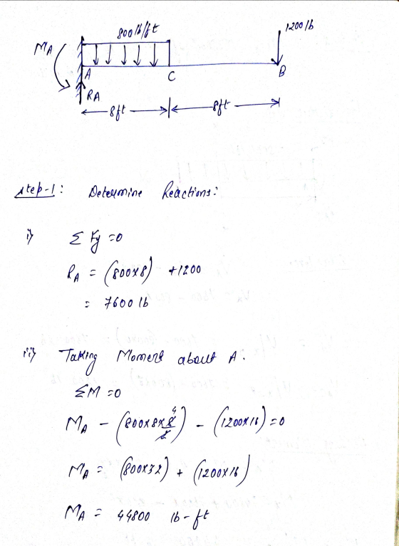
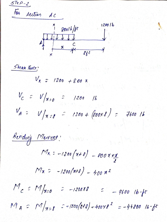
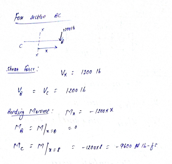
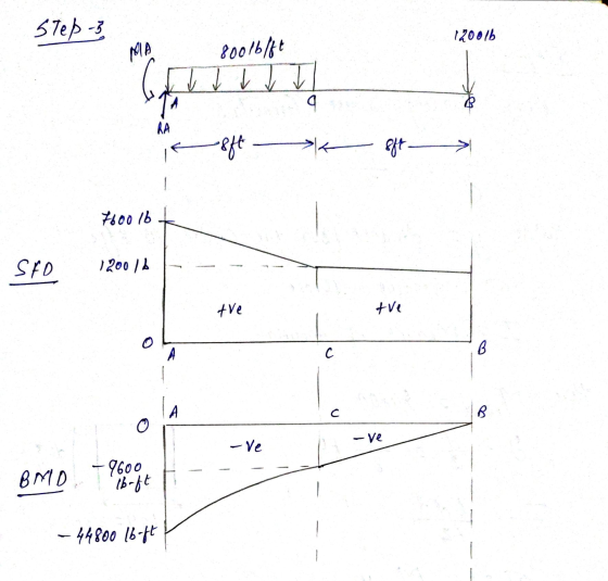
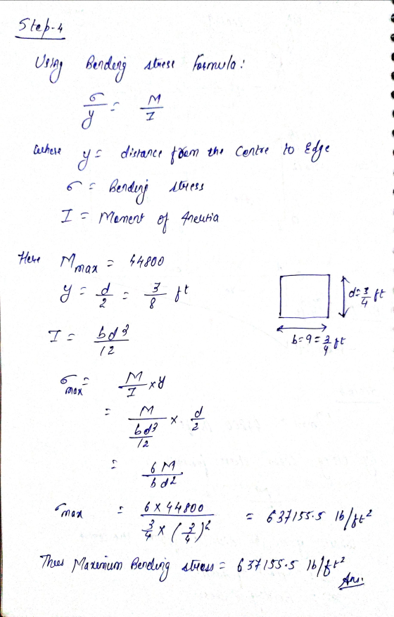
4. A cantilever beam is loaded as shown in the figure. Using the method of sections...
Question 1 1. A steel beam is loaded as shown complete the following a. Draw a...
 Question 1 1. A steel beam is loaded as shown complete the following a. Draw a neat shear force and bending moment diagrams using area moment method b. Determine the maximum bending stress, clearly indication where this occurs c. Determine the maximum shear stress clearly indication where this occurs d, Plot the bending and shear stress for the cross section at x = 5 ft. from the left hand support e. Using area moment method, determine the deflection at the...
A beam having a T-Section is loaded as shown in figure below.
 A beam having a T-Section is loaded as shown in figure below. a. Draw the Shear Force & Bending Moment Diagram b. Locate the Nuetral Axis c. Find the maximum tensile and compressive bending stress d. Find the maximum shear stress e Find the Bending Stress and Shear Stress at the points marked on the cross section
2. A cantilever beam is loaded as shown in the following figure. 1) Draw the shear...
 2. A cantilever beam is loaded as shown in the following figure. 1) Draw the shear force and bending moment diagrams 2) Calculate the maximum bending stress in the beam. S 3) Calculate themaximum transverse shear stress in the beam. 19 kN 3 kN/m NA 01 m 2 m 2 m 2 m
4. A T-shaped cross-sectional beam is loaded as shown in the figure. Determine the following a....
 4. A T-shaped cross-sectional beam is loaded as shown in the figure. Determine the following a. Sketch the internal shear force and bending moment diagrams for the beam. b. Calculate the maximum magnitude of the bending stress. Indicate where this occurs on the cross-section and along the length of the beam. c. Calculate the transverse shearing stress at the centroid of the cross-section using the maximum magnitude of the transverse shear force. - 200 mm 8 KN 1.5 kN/m 20...
Q3 (25 pts) 3. For the cantilever beam shown below and to the left, Determine the...
 Q3
(25 pts) 3. For the cantilever beam shown below and to the left, Determine the reactions at the wall at C. Draw the shear (V) and moment (M) diagram for the beam and label the appropriate values. For the given cross section, determine the magnitude of the maximum COMPRESSIVE bending stress and state where this occurs along the length of the beam and along the height of the beam (top or bottom). Sketch the NORMAL stress distribution (profile) for...
Q3
(25 pts) 3. For the cantilever beam shown below and to the left, Determine the reactions at the wall at C. Draw the shear (V) and moment (M) diagram for the beam and label the appropriate values. For the given cross section, determine the magnitude of the maximum COMPRESSIVE bending stress and state where this occurs along the length of the beam and along the height of the beam (top or bottom). Sketch the NORMAL stress distribution (profile) for...
Problem 1 For the loaded beam with the cross-section shown: A. Find the location of the neutral a...
 Problem 1 For the loaded beam with the cross-section shown: A. Find the location of the neutral axis B. Compute the moment of inertia of the section around the neutral axis C. Locate the section of maximum moment then compute the maximum stress due to bending, fb D. Locate the section of maximum shear-compute the shear stress at the neutral axis 3.0 k 8" 1.5 k/ft 1.0 k/ft 2" 8 10 ft 6 ft 4 ft 2" Cross-Section
Problem 1...
Problem 1 For the loaded beam with the cross-section shown: A. Find the location of the neutral axis B. Compute the moment of inertia of the section around the neutral axis C. Locate the section of maximum moment then compute the maximum stress due to bending, fb D. Locate the section of maximum shear-compute the shear stress at the neutral axis 3.0 k 8" 1.5 k/ft 1.0 k/ft 2" 8 10 ft 6 ft 4 ft 2" Cross-Section
Problem 1...
Problem 1. Consider the beam cross sections shown in figures (a) and (b). If the material...
 Problem 1. Consider the beam cross sections shown in figures (a) and (b). If the material comprising beams with these cross sections has allowable bending stress Allow = 25000 psi, either in tension or compression, determine the maximum bending moment each beam can carry. Assume elastic behavior. Take D=6 in. Problem 2. The beam shown has the cross-section indicated. Indicate the location along the beam where the maximum and minimum normal stresses occur in the beam. Determine the values of...
For the beam shown in the given figure:
 For the beam shown in the given figure: (a) Express the internal shear (V) and moment (M) in the beam as a function of x. (b) Draw the shear force diagram (SFD) and bending moment diagram (BMD). (c) If the area moment of inertia (I) of the beam's cross section about the neutral axis is 301.3 (10-6)m4, determine the absolute maximum bending stress (σmax) in the beam.
I-beam loaded as a cantilever beam 2. An I-beam is loaded as a cantilever beam as shown below. The cross-section of the...
 I-beam loaded as a cantilever beam
2. An I-beam is loaded as a cantilever beam as shown below. The cross-section of the beam is also shown. Indicate on both illustrations, by circling and labeling, the location of the maximum tensile stress and the maximum compressive stress.
2. An I-beam is loaded as a cantilever beam as shown below. The cross-section of the beam is also shown. Indicate on both illustrations, by circling and labeling, the location of the maximum tensile...
I-beam loaded as a cantilever beam
2. An I-beam is loaded as a cantilever beam as shown below. The cross-section of the beam is also shown. Indicate on both illustrations, by circling and labeling, the location of the maximum tensile stress and the maximum compressive stress.
2. An I-beam is loaded as a cantilever beam as shown below. The cross-section of the beam is also shown. Indicate on both illustrations, by circling and labeling, the location of the maximum tensile...
a. Draw a free-body diagram for the beam shown above and derive expressions for the support...
 a. Draw a free-body diagram for the beam shown above and derive
expressions for the support reactions at A and B
b. Draw internal force (shear and bending moment) diagrams.
c. If a = 10 ft and M0 = 200 ft-lb, use the dimensions of the
beam cross-section, provided on the previous page, to compute the
maximum flexural and shear stresses on the beam cross-section.
d. If the allowable bending stress is 925 psi and the allowable
shear stress is...
a. Draw a free-body diagram for the beam shown above and derive
expressions for the support reactions at A and B
b. Draw internal force (shear and bending moment) diagrams.
c. If a = 10 ft and M0 = 200 ft-lb, use the dimensions of the
beam cross-section, provided on the previous page, to compute the
maximum flexural and shear stresses on the beam cross-section.
d. If the allowable bending stress is 925 psi and the allowable
shear stress is...
 Question 1 1. A steel beam is loaded as shown complete the following a. Draw a neat shear force and bending moment diagrams using area moment method b. Determine the maximum bending stress, clearly indication where this occurs c. Determine the maximum shear stress clearly indication where this occurs d, Plot the bending and shear stress for the cross section at x = 5 ft. from the left hand support e. Using area moment method, determine the deflection at the...
 2. A cantilever beam is loaded as shown in the following figure. 1) Draw the shear force and bending moment diagrams 2) Calculate the maximum bending stress in the beam. S 3) Calculate themaximum transverse shear stress in the beam. 19 kN 3 kN/m NA 01 m 2 m 2 m 2 m
 4. A T-shaped cross-sectional beam is loaded as shown in the figure. Determine the following a. Sketch the internal shear force and bending moment diagrams for the beam. b. Calculate the maximum magnitude of the bending stress. Indicate where this occurs on the cross-section and along the length of the beam. c. Calculate the transverse shearing stress at the centroid of the cross-section using the maximum magnitude of the transverse shear force. - 200 mm 8 KN 1.5 kN/m 20...
 Q3
(25 pts) 3. For the cantilever beam shown below and to the left, Determine the reactions at the wall at C. Draw the shear (V) and moment (M) diagram for the beam and label the appropriate values. For the given cross section, determine the magnitude of the maximum COMPRESSIVE bending stress and state where this occurs along the length of the beam and along the height of the beam (top or bottom). Sketch the NORMAL stress distribution (profile) for...
Q3
(25 pts) 3. For the cantilever beam shown below and to the left, Determine the reactions at the wall at C. Draw the shear (V) and moment (M) diagram for the beam and label the appropriate values. For the given cross section, determine the magnitude of the maximum COMPRESSIVE bending stress and state where this occurs along the length of the beam and along the height of the beam (top or bottom). Sketch the NORMAL stress distribution (profile) for...
 Problem 1 For the loaded beam with the cross-section shown: A. Find the location of the neutral axis B. Compute the moment of inertia of the section around the neutral axis C. Locate the section of maximum moment then compute the maximum stress due to bending, fb D. Locate the section of maximum shear-compute the shear stress at the neutral axis 3.0 k 8" 1.5 k/ft 1.0 k/ft 2" 8 10 ft 6 ft 4 ft 2" Cross-Section
Problem 1...
Problem 1 For the loaded beam with the cross-section shown: A. Find the location of the neutral axis B. Compute the moment of inertia of the section around the neutral axis C. Locate the section of maximum moment then compute the maximum stress due to bending, fb D. Locate the section of maximum shear-compute the shear stress at the neutral axis 3.0 k 8" 1.5 k/ft 1.0 k/ft 2" 8 10 ft 6 ft 4 ft 2" Cross-Section
Problem 1...
 Problem 1. Consider the beam cross sections shown in figures (a) and (b). If the material comprising beams with these cross sections has allowable bending stress Allow = 25000 psi, either in tension or compression, determine the maximum bending moment each beam can carry. Assume elastic behavior. Take D=6 in. Problem 2. The beam shown has the cross-section indicated. Indicate the location along the beam where the maximum and minimum normal stresses occur in the beam. Determine the values of...
 I-beam loaded as a cantilever beam
2. An I-beam is loaded as a cantilever beam as shown below. The cross-section of the beam is also shown. Indicate on both illustrations, by circling and labeling, the location of the maximum tensile stress and the maximum compressive stress.
2. An I-beam is loaded as a cantilever beam as shown below. The cross-section of the beam is also shown. Indicate on both illustrations, by circling and labeling, the location of the maximum tensile...
I-beam loaded as a cantilever beam
2. An I-beam is loaded as a cantilever beam as shown below. The cross-section of the beam is also shown. Indicate on both illustrations, by circling and labeling, the location of the maximum tensile stress and the maximum compressive stress.
2. An I-beam is loaded as a cantilever beam as shown below. The cross-section of the beam is also shown. Indicate on both illustrations, by circling and labeling, the location of the maximum tensile...
 a. Draw a free-body diagram for the beam shown above and derive
expressions for the support reactions at A and B
b. Draw internal force (shear and bending moment) diagrams.
c. If a = 10 ft and M0 = 200 ft-lb, use the dimensions of the
beam cross-section, provided on the previous page, to compute the
maximum flexural and shear stresses on the beam cross-section.
d. If the allowable bending stress is 925 psi and the allowable
shear stress is...
a. Draw a free-body diagram for the beam shown above and derive
expressions for the support reactions at A and B
b. Draw internal force (shear and bending moment) diagrams.
c. If a = 10 ft and M0 = 200 ft-lb, use the dimensions of the
beam cross-section, provided on the previous page, to compute the
maximum flexural and shear stresses on the beam cross-section.
d. If the allowable bending stress is 925 psi and the allowable
shear stress is...
Most questions answered within 3 hours.
-
Calculate the approximate number of residues of Rubisco, which
is involved in carbon fixation in plants,...
asked 1 minute ago -
Other decisions about scientific claims can have a much broader
impact.ENERGYarrow-10x10.png, environment, health, security - all...
asked 56 minutes ago -
I need to write a research paper and work cited about this
topic: The United States...
asked 1 hour ago -
Hello! I was wondering if I could have some help?
If the vapor pressure of carvone...
asked 1 hour ago -
An economist wants to estimate the mean per capita income (in
thousands of dollars) for a...
asked 2 hours ago -
What would be the input/output characteristic of a circuit
obtained by putting two of your 2's-complementers...
asked 1 hour ago -
In Drosophila, the transition from the syncytial blastoderm
stage to the cellular blastoderm stage is a...
asked 2 hours ago -
Project management question:
Name 3 different types of resources (hint: humans are one
type)
asked 2 hours ago -
Consider the following reaction: C 2H 2( g) + 2H 2( g) C 2H 6(
g)...
asked 2 hours ago -
Consider a 1.0 L buffer containing 0.092 mol L-1 HCOOH and 0.100
mol L-1 HCOO-. What...
asked 2 hours ago -
Koch Realty has owned a vacant land with a FMV of
$775,000 and an adjusted basis...
asked 3 hours ago -
It is estimated 29% of all adults in United States invest in
stocks and that 85%...
asked 3 hours ago